How To
There are some known issues when working with the PLM and PWB CATIA connector. Whilst we are working on a resolution we have documented them at the link here, along with our suggested workarounds.
We have also documented any known CAD issues and potential workarounds. These have been reported to the tool provider in the aim to receive a fix in future releases.
If you find other issues or improved workarounds please email us at plm-support@cern.ch so that we can investigate any problems and share the information with all other users through this document.
During the SmarTeam to PLM transition, a number of your already experienced colleagues will have the mandate as local supporters and some time dedicated to help you get started.
To find your closest local supporter, please see the list following this link.
Before working in the PLM please follow the available training material depending on your usage and requirements. The trainings can be found here.
Below is a list of acronyms that are used in relation to CATIA.
- BOM – Bill of Materials
- CGR – CATIA Graphical Representation
- GSD – Generative Shape Design
- PWB – PDM Workbench (PLM-CATIA connector)
- TBE – Titleblock Editor
- WB – Workbench
See the list of PLM Acronyms here.
See the list of SmarTeam Acronyms here.
Below is a list of acronyms that are used in relation to the PLM.
- BOM – Bill of Materials
- CDR – CERN Drawing Reference → Replaces CDD Number
- DC – Design Code
- Doc – Document
- DT – Digital Twin
- LC – Lifecycle
- PC – Profile Card
- PWB – PDM Workbench (PLM-CATIA connector)
- QAC – Quality Assurance and Control
- RFC – Ready for Check
- RFC in PLM – Ready for Check in PLM
- RPG – Responsible Project Group
- TBE – Titleblock Editor
- TOC – Table of Contents
- WF – Workflow
- Pre-migrated – SmarTeam documents are now available in the PLM, but still owned by SmarTeam
- Migrated – Documents have been pre-migrated and changed ownership to the PLM.
See the list of CATIA Acronyms here.
See the list of SmarTeam Acronyms here.
To access CATIA via the PLM please press the CATIA icon in the top right of the dashboard screen.

Access to the CATIA connector is granted on request, therefore if you have not already done so please complete this form to work with CATIA. Prior to granting you access, we would ask for you to complete the relevant training, please see a link to the learning path to find the best suited course for you. Once you have been granted access you will have to download the required programs from CMF.
If you do not have the connector installed, or it is an out of date version, you will receive the following message when attempting to launch CATIA through the button on the PLM dashboard. This will remind you which applications must be installed and a link to CMF. There is also a link to documentation explaining the prerequisites required before running this application.

If CATIA is not installed the launch button will be greyed out.
PLM users can directly request Design Code access from the PLM platform through a dedicated access request interface.
- Open the Design Code for which access is required and click the new green “Request Access” button.
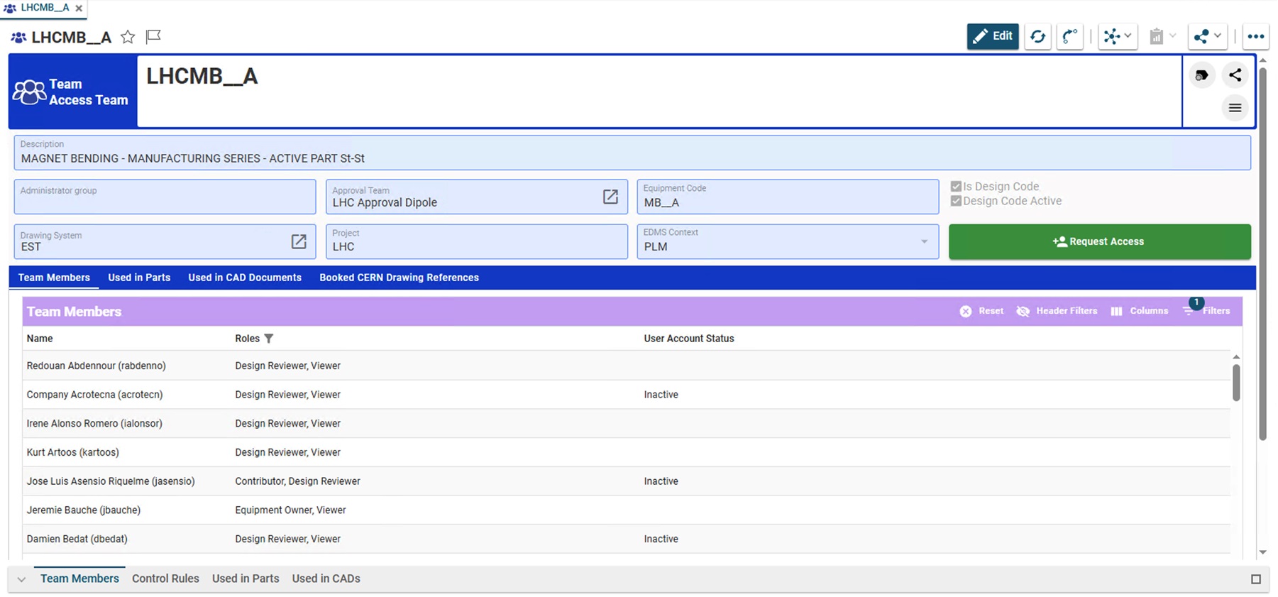
- Perform the access request for one role at a time.
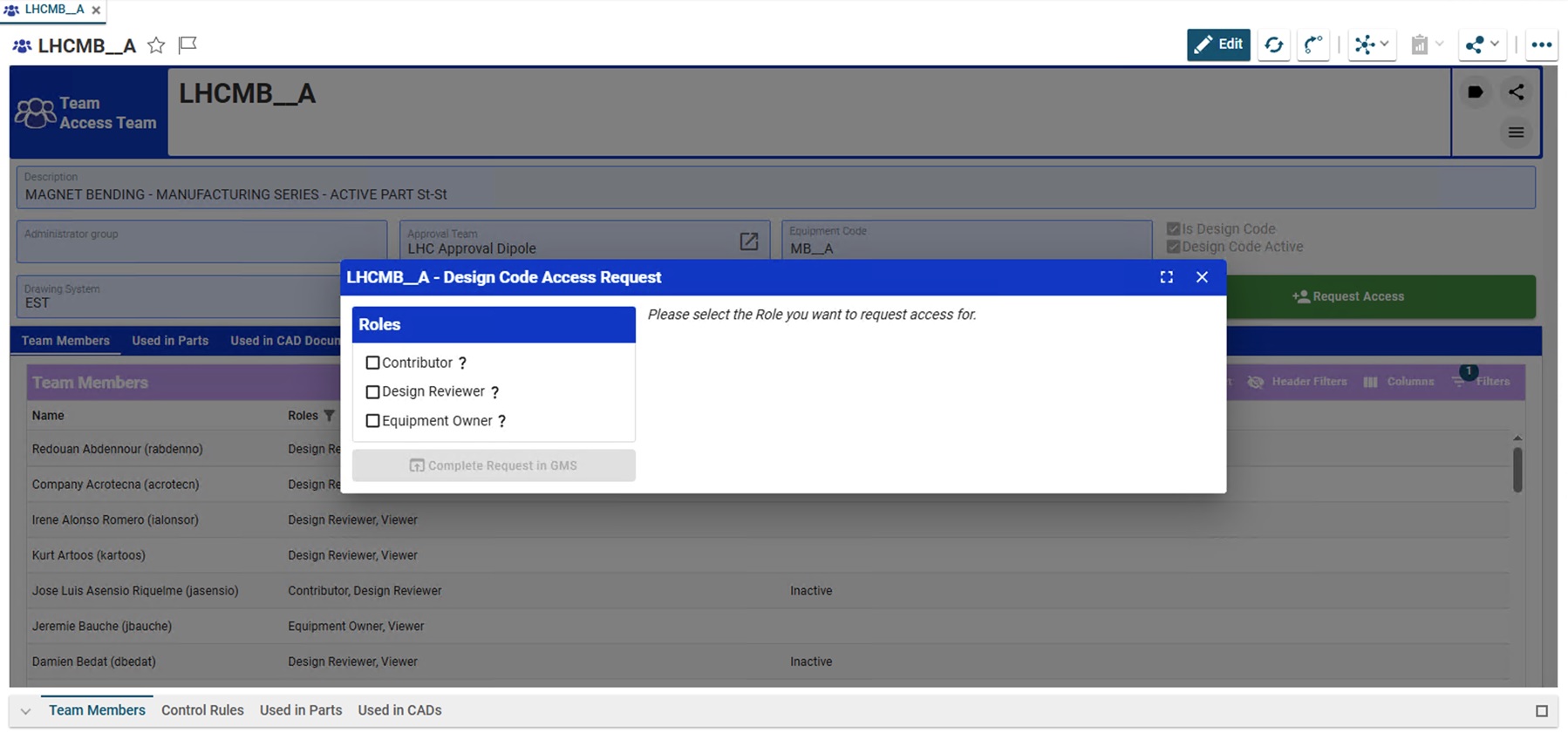
- If a "Role" is assigned to different Groups, it is needed to chose a specific one. As soon it is selected, the "Complete Request in GMS" button becomes available.
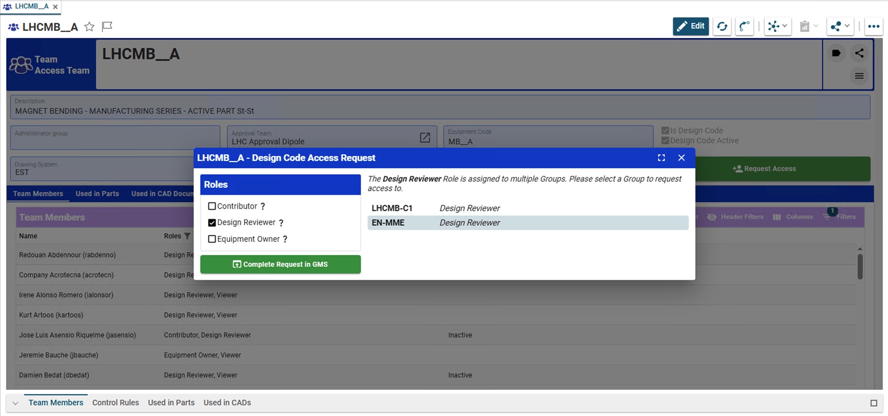
- It redirects you to the GMS website where you can subscribe to the group providing a justification.
The administrators of the group will be responsible for handling your request and you'll get notified by email as soon as a decision is taken.
The PLM and CATIA are connected through the connector, PDM Workbench (PWB).
There is a toolbar and different workbenches for the various CATIA workbenches (Part Design, Assembly design, drafting). The PDM workbenches do not contain any modelling tools, but have tools to manage the documents such as saving, duplication and viewing the PDM properties. This FAQ will explain all the tools available in the PWB.
More: FAQ
The following conditions apply to documents shared via Public Link.
- The Public Link must be created from an Approved Design Collection with related Part in Approved or Released state.
- Draft or non-approved documents are not eligible for external sharing.
- Only documents attached to that Design Collection are allowed for exchanging.
- Documents are automatically compiled into a ZIP file at the time the link is accessed.
Access Restrictions:
- No CERN authentication is required for external users.
- The link provides download-only access.
- Access is restricted solely to the generated link.
- Documents are accessible only until the defined expiration date. Once expired, the link becomes inactive and documents are no longer accessible.
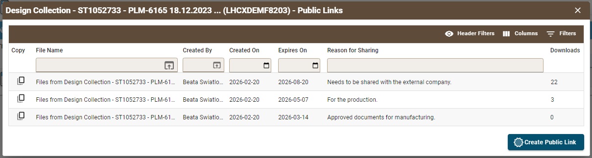
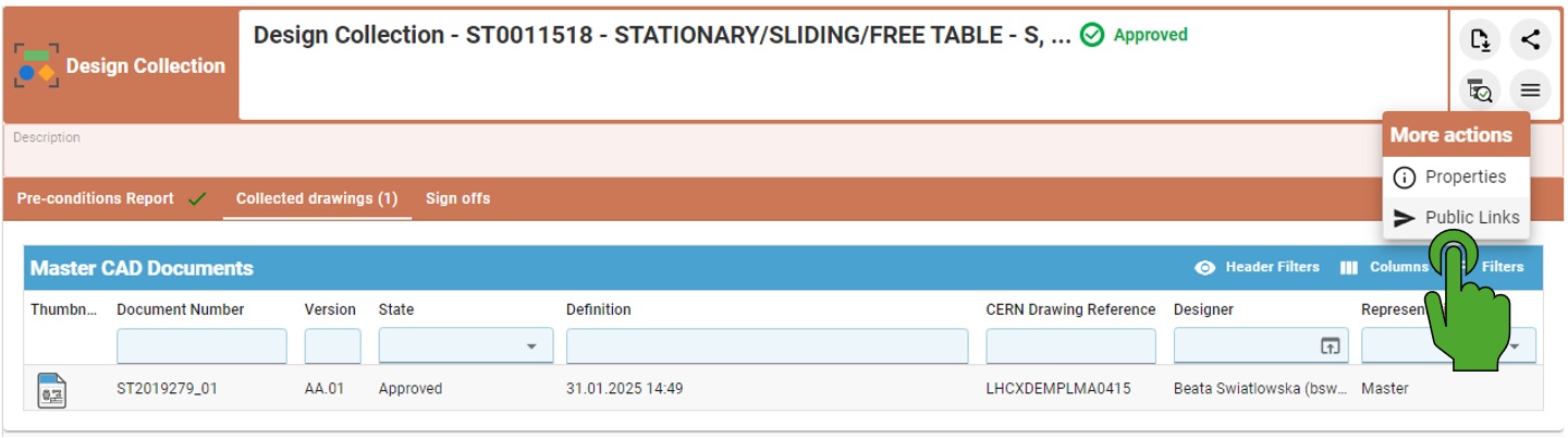
By opening the Design Collection with the created before Public Links, it is possible to access them again by clicking on the left top button "More actions" (with three lines) and then choosing the Public Links.
If the Public Link has been already created, it will open the new window with all the existing links. From there it is possible to copy the URL again.
Public Links must be created from an Approved Design Collection.
-
Open the approved Design Collection.
-
In the top-left corner of the profile card, click “More actions” (three-line menu).
-
Select “Public Links”.
-
A creation window opens with the related Design Collection automatically added.
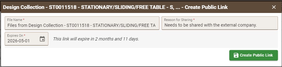
In the creation window, users must:
-
Modify the file name (optional).
-
Provide a reason for sharing (minimum 10 characters and it is mandatory).
-
Define the expiration date.
-
Minimum: 1 day
-
Maximum: 6 months
-
After completing the required fields:
-
Click the “Create Public Link” button.
-
The system generates the Public Link.
-
Copy the link to the clipboard and share it with the external partner.
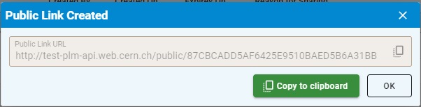
When the link is opened in any browser, the external user can directly download a ZIP file containing the documents related to the Part without authentication required.
Sometimes, when saving from CATIA in the PLM, the list of Folders in the SAVE window is empty, while you do have several Folders flagged as favourite in the PLM:

This usually comes from the fact that one of the Folders flagged as favourite, has since been deleted.
In the PLM, go to the list of favourite Folders and try to access each of them.
If you find one that has been deleted, you will get this message:

Then, use the contextual menu to remove this favourite from the list:

Check all the favourite Folders.
Then, go back to CATIA, and run the SAVE command again.
The list should now be okay:

To prevent data loss caused by save interruptions (for example, switching windows too quickly after pressing "Save"), a CATIA Connector update was deployed on Wednesday, 5th of November. This update introduces a temporary but safer save mechanism.
Key Changes Implemented
Save Dialog is now mandatory for ALL save operations
- Previously, the Save Dialog appeared only on the first save to PLM Platform.
- The follow-up saves were handled via an asynchronous upload mechanism, which has now been removed.
Synchronous save process enforced
- Users must now wait until the file upload is fully completed before continuing.
- CATIA Connector icons will no longer blink during the save process.
Save must be explicitly confirmed
- After clicking Save (or CTRL + S), users must not switch CATIA windows or use CTRL + TAB.
- Wait until the “Save to PDM?” dialog appears.
- If the dialog does not appear, click Save again and wait.

- The save operation is validated only when the dialog informs the user of "Action succeeded" in the button left corner.

- Do not navigate away to another CATIA window until the process completes.
- You may then safely close the dialog.

Save Dialog Feedback Types
The Save Dialog Summary may show different feedback:
Type 1 – Modifications to an existing PLM document are being saved.
Type 2 – A new document is being saved; the PDM Create window will open after Save.
Type 3 – No save occurs because the document is read-only (unclaimed; “Locked By” is empty).
Type 4 – The operation shows Create, but the document already exists in PLM.
- If the CATIA Part Number starts with “ST” and no duplicate operation was performed, the document is not recognized by the connector and will be saved under a new reference.


To change the Design Code assigned to a Part follow the steps below:
- Switch to Edit Mode by clicking the "Edit" button located in the top-right corner of the Profile Card.

- Select inside the Design Code box (not on the icon). This will open a new dialog displaying all the Design Codes for which the user has Contributor rights in.


- Choose the Design Code from the list and click on "Save" on the Profile Card to apply the new one.
Note, in Edit mode, the icon next to the Design Code field opens the current Design Codes profile card. It cannot be used to search and select a new code.

Note:
If you would like to learn more about how to propagate the Design Code to BOM dependencies, please check the link below:
How to add and propagate the Design Code?
In the PLM Platform there are two ways to add a Design Code to a Part, and one method to add and propagate it down to the child Parts:
- by the Pen Tool

- It is possible to use it to propagate the Design Code through the BOM dependencies.
- It can be used outside of Edit mode, therefore can be used on frozen parts. (You still require the necessary access rights)
- It is useful for migrated Parts (they are frozen when first migrated).
- It can't be used if the Part already has a Master drawing attached.
- This tool is NOT for changing the Design Code that is already exists on the Part.
- If you want to know how to change the Design Code, please check the link below:
How to change the Design Code?
- If you want to know how to change the Design Code, please check the link below:
- by the Edit Mode

- It only affects the current Part and it doesn't propagate through the BOM.
- It can't be used with frozen Parts.
- It can be used when the Part has already a Master drawing attached.
- If there is already the Design Code on the Part, it is possible to change it with the Edit mode.
Adding and propagating Design Codes using the Pen Tool
Selecting the small pen icon will display a new dialog with two options.


- It sets the Design Code only on the current open Part.
- It sets the Design Code on the current open Part, and propagates it to all BOM dependencies WITHOUT a Design Code or master drawing.
Setting and updating Design Codes in Edit Mode
To set the Design Code in Edit Mode, click the "Edit" button in the right top corner of the Profile Card, then select in the Design Code box (not on the icon). This opens a dialog showing the Design Codes search, for which the user has Contributor rights in. A selection can then be made.
Note, in Edit mode, the icon next to the Design Code field opens the current Design Codes profile card. It cannot be used to search and select a new code.
Below are the different drawing labels that can be assigned to a drawing via the 'Assign drawing label' workflow.
- As Built: Represents how the equipment or services is/are installed and operated
- For Information: Given for information only
- For Tender: Valid for tendering process
- For Execution: Valid for manufacturing (if representing an equipment) or for execution (if representing a facility or some services)
- Obsolete: The design has been phased out
- For production: Valid for manufacturing in series
- For installation: The equipment or the facility can be installed as represented
Complete documentation: Assign Drawing(s) Label Workflow FAQ
When launching a workflow to approve data in the PLM, a precondition report is ran to ensure that the data is in a suitable state and all the workflow pre-requirements are met.
If the report finds an error, this must be resolved before the workflow can be launched.
Below details some of the common causes of the errors, and how to fix them:
- Checking control rules
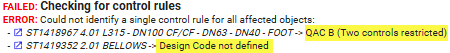

The control rules (defined via the design code) must be the same for all Parts- Commonly this is caused because no design code is defined for one or more of the affected Parts (therefore no control rule). Check below further in the report for the 'check design code' section, and assign a design code to any Part with a missing one (see bullet point below).
- If like the second image, its caused by two or more different control rules being defined, you must split up the workflow. Firstly launch and complete another workflow for the Part with the differing control rule, then resume the original workflow to approve the remaining objects.
- Checking Design Code

All objects must have a design code assigned- Assign a design code to all the Parts without one (the CADs & Documents will inherit from its Parent Part).
- Assign a design code to all the Parts without one (the CADs & Documents will inherit from its Parent Part).
- Not latest version versions

In preparation documents that will be impacted by the workflow must be the latest version- Check the status of all the objects in the Check dependency
 tree to find how the non-latest version is linked to the structure. If its parents are all in preparation, then you need to update the structure.
 - Note often this can be caused because a drawing has not been updated and it still pointed to the non latest 3D version.
- If its parent is Approved or Replaced, then contact PLM Support as it can either be due to a migration or data quality issue in SmarTeam.
- Check the status of all the objects in the Check dependency
- Drawing save date

A drawing must be saved after the pointed 3D document- Update the drawing so that the latest update on its dependency (3D) is taken into account.
- Open and claim your Drawing.
- Update your views and save it once before to make sure that a new version is created.
- Run the TBE – Generate & Save
- Update the drawing so that the latest update on its dependency (3D) is taken into account.
- Checking state of collected items

Objects can not already be 'in review' state via another workflow- Complete the outstanding workflow to either approve or reject the concerned Part/CAD Document first.
- Complete the outstanding workflow to either approve or reject the concerned Part/CAD Document first.
Complete documentation: Design Verification Workflow FAQ
Usually, when working with CATIA and the PLM, the Bill Of Materials is updated automatically after each CATIA save via the PWB connector (e-BOM sync).
This is the case for all new CAD Documents created and modified in the PLM.
However, for the CAD structures coming from SmarTeam, the situation is slightly different.
Indeed, sometimes in SmarTeam, the BOM was manually managed or modified (Item manually added, quantity manually modified...) and to make sure that the migrated version of the BOM is retained in the PLM, no automatic update was triggered based on the CAD Structure. On the contrary, the BOM was rebuilt as it was in SmarTeam and it appears in the PLM as manually managed.
Also, since the CAD Documents coming from the SmarTeam have not been modified (saved) in the PLM during the migration process, the automatic BOM update has never been launched.
As a result, for the migrated CAD Structure, the BOM is set to manually managed. It means that for a given Part corresponding to a migrated CAD, all its dependencies (the BOM) are flagged with the attribute "Manually managed".

And then, even if a new version of this Part is created (manually, or because a CAD is versioned) the BOM will remain manually managed.
Leading in possible error when updating the BOM with the creation of duplicated links to the same dependency:

If you want to update your BOM, and to come back to an automatic update of the BOM after the CAD Document structure is saved in CATIA, here are the steps to follow:
- Create a new version of the Part / CAD parent.
Either manually create a new version of the parent Part from its profile card in the PLM, or create one indirectly from CATIA by creating a new version of the CAD Document. This will trigger a new version of the Part automatically (since the migrated Part versions are frozen).
- From the new version of the Parent Part, edit the Profile Card and expand the relationship grid (at the bottom) and go to the BOM tab.
There, remove all the ticks in the manually managed column.
(Keep the ticks in the Pos & Qty Override columns if you want to retain this information from the Smt BOM)

- Save the CATProduct from CATIA (or if already done, run the BOM Sync from the CAD Doc Profile Card).
- Check the result.
And, if needed, refer to the previous version of the Part to see how was the BOM right after the Migration.
All dependencies in CATIA should be back in the BOM. If some are missing, there can be several reasons, such as:
1. Some Parts might have been added manually in SmarTeam with no corresponding CAD Doc in the CAD Structure (e.g. glue): add them manually again in PLM (if relevant).
2. Some components in CATIA are not Master, then their Part are not automatically added in the BOM: mark those as 'In-BOM' in CATIA and save the CATProduct again.


3. The BOM cannot be computed because your Assembly is not up-to-date (children with red dot) or the CATIA save window reports another error: check if your assembly is using only the current version of the dependencies.
See the FAQ below for more information on these BOM management processes.
This process has to be done only once after the migration.
Once a Part's BOM has been re-computed once after migration using the PLM e-BOM sync, then each new CATIA Save will update the BOM.
If you're experiencing delays or failure when saving through the standard CATIA Connector, you can use the Emergency Save (also called Toolbox) function as a fallback to manually upload your work.
You can also use this tool to open existing CAD Documents for which you already experienced issues when opening or saving.
This guide walks you through the required steps, important limitations, and best practices to ensure your data is securely backed up.
Known Limitations
- No New Documents: The Toolbox will not handle new (never saved) CAD documents. These must be handled with the standard CATIA Connector before using this feature (see below).
- No BOM Computation will be launched after the save via the Toolbox. And running the e-BOM sync from the Profile Card of the assembly will not work.
So, at a point in time, it will be mandatory to save your structure with PWB, or to consider to update your BOM manually. - The CAD Documents open in CATIA using the toolbox will not display any PLM metadata in the CATIA tree, and appears as “Not in PDM”, thus cannot be saved using the usual CATIA Connector save. But they can be saved via the toolbox.
Using the Toolbox Save Command
If after a regular CATIA Connector save, you notice a failure, you can use the Toolbox Save Command.
The connector will save all the CAD Documents which are claimed in PLM AND modified in the CATIA Session before uploading them in the PLM.
- Let your CATIA session running. DON’T log off from the Catia Connector.
- Close the CATIA Connector Save window (if relevant).
- Access the tool, following this path in your file explorer:
\\cern.ch\dfs\Applications\PLMApps\CATIAPLMToolbox
and click on StartCATIAPLMToolbox_v1.exe
Note: for a regular usage, you can copy this shortcut on your desktop:
StartCATIAPLMToolbox.bat - Shortcut.lnk - The tool will start and will be associated to the PLM Desktop:

- Click the Save & Upload button.
- Read carefully the report and check the result in the PLM.

In case of doubt, call the CAD & PLM Support team.
Using the Open Command
- Open the CATIA session (or if CATIA is already running, use this session).
You do not have to log-in to the PWB CATIA Connector. However, if you want to work with PWB with other CAD Documents or if you will have to save brand new CAD Documents to the PLM, you must log-in. - Access the tool following this link:
\\cern.ch\dfs\Applications\PLMApps\CATIAPLMToolbox\StartCATIAPLMToolbox_v1.exe
Note: for a regular usage, you can copy this shortcut on your desktop:
\\cern.ch\dfs\Applications\PLMApps\CATIAPLMToolbox\StartCATIAPLMToolbox.bat - Shortcut.lnk - Click on Open and use the filters in the new pop-up window that appears to find the CAD document to open.
- Select it and in the “Open in CATIA” window, choose the expand strategy and the options you need, then validate.
- The tool will download the necessary files to your local machine then will open the selected CAD Document in CATIA.
Attention, CAD Documents open via the toolbox can only be saved with the toolbox. (And not via the usual CATIA Connector save)
Using the Open Profile Card Command
- Select one or several Documents or instances node in CATIA (the selection of features in a CATPart will be ignored)
- Click on the Open Profile Card button.
The Profile Card(s) corresponding to your selection will be displayed in the PLM Desktop.
Best Practices
- Use the Toolbox only as a last resort when standard saving is not responding, reports an blocking error or is taking too long or if you already experienced an issue when working with the same CAD Document.
- Always verify the saved structure afterward within the CATIA Connector interface.
Check for each of your recent modified and saved CAD Documents that the date & time of last modification of the native file is coherent with the save time.

- Notify the PLM Support Team if you consistently encounter performance issues or errors with the standard CATIA Connector.
- When you are aware that opening a given CAD Document returns an error, open directly via the Toolbox.
- In case you have inserted a new CAD Doc in your CATIA structure you are about to save with the toolbox:
Open this new CAD Doc in the new CATIA Window, save it using the CATIA Connector, and come back to the assembly window to save the assembly with the toolbox.
If you need further assistance, please reach out to our support team via the Contact Page or consult the detailed troubleshooting guide for CATIA connector issues.
There are multiple ways to link a Folder or Content ( Part, Document, or CAD Document) to an existing Folder, with the prerequisite that you have the necessary rights to edit this Folder:
- For the Part & CAD Documents, when these objects are created using one of the CAD connectors. The first Save action allows you to select a Folder and to link either the Part, or the CAD Document (or both) to this Folder.
Refer to the dedicated documentation of each connector for more info. Example for CATIA PWB.
- When importing a new object from a batch import.
Refer to the dedicated documentation for more details.
Also, at any time, you can create a link using one of the following method from the PLM:
- From the Profile Card of the folder:
Edit the Profile Card and expand the Relationship grid.
Go to the appropriated tab, depending the nature of the object you want to attach ("Folders" or "Content").
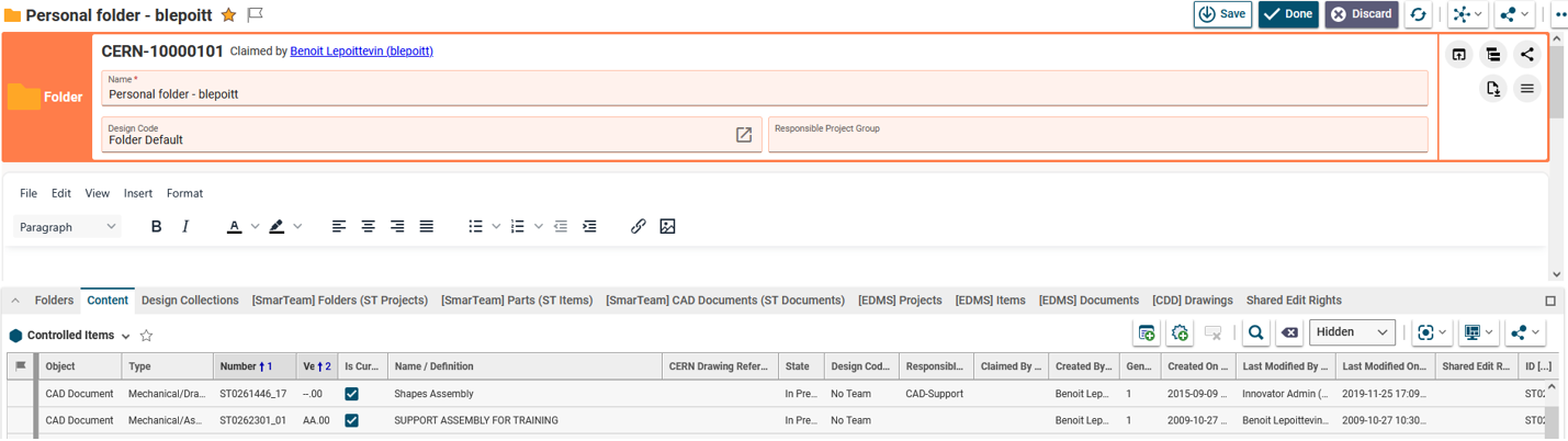
Then click on the "Add Folders" / "Add Controlled Items" button
And search for the object you want to attach in the Select Items window. Then click OK to come back to the Profile Card.
Click Save / Done on the top of the Profile Card so that the changes are saved.
- From the tree navigator:
From any Folder tree view, you can select a Folder in the tree and from the contextual menu, click on "Pick Item":

Then select the type of Object you want to attach and search for it in the search window.

Click OK to come back to the Profile Card.
Note: you do not have to Edit and Save the Folder using this method, nevertheless, you must have the Edit rights to perform the action.
There is 2 ways to get access to the Excel EBOM Export tool:
1. From a Part Profile Card, in the "Share" menu:

2. Or from the Part search grid.
A. open the search grid:

B. search for your Part.
C.use the contextual menu

- Navigate to the Table of Content (TOC) in the PLM, and go to the Part search:

- In the Search Parts tab, go to the Refine menu and select All or Extended.

Then, select the SCEM or any other missing property in the list.
The selected properties will then be added as new columns in the main grid.
- You can now search for some Parts using these additional properties.

The “Design Collection” functionality in PLM has been introduced to replace the EDMS Drawing Folders functionality. However it is still possible to use an EDMS Drawing Folder together with a PLM design collection as described hereafter.
Detailed information about the PLM functionality can be found here: Design Collection FAQ
If you still require the EDMS Drawing Folder, you can link the PLM Design Collection directly to it:
1. Copy the link of the Design Collection:

2. Add the link of the Design Collection to the EDMS Drawing Folder:

3. Release the EDMS Drawing Folder to ensure traceability.
Current limitation: Access to PLM data can't be given to users with light-weight accounts like in EDMS, if this is required, please contact support to find a suitable solution for your case.
The plotting from EDMS Drawing Folders and Caddie is currently not compatible with PLM drawings. Instead of plotting PLM data from EDMS, once the “Design Collection” is filled in and approved in the PLM, you can perform the following steps to send a collection of drawings to any plotter:
- Download the converted/stamped files to your local machine: How to extract / download files from the PLM?
- Print the Drawings on any plotter, following the standard methodology: How to print multiple drawings at once with PDF X-Change Editor?
The dashboard is the main page you will be greeted with when you open the PLM, it contains a search table.
The images below explain the different options and filters you can use to enhance your search.
This page will search for all items types:
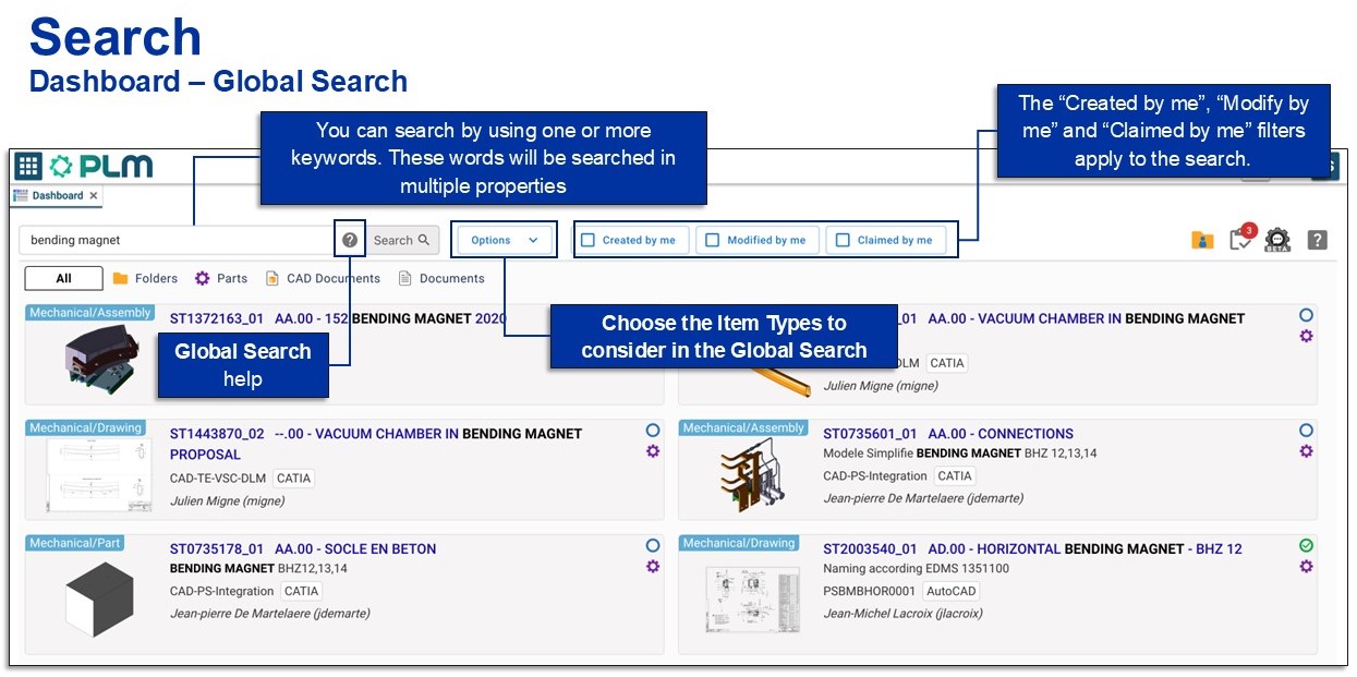
You can also narrow down the search straight away by selecting one of the specific item type tabs.

![]() Search Navigation and preferences in the PLM
Search Navigation and preferences in the PLM
See other 'searching' how-tos here
You can duplicate an entire structure using the following tool from the PDM workbench contextual menu. It will duplicate the entire structure, top down from the selected node.
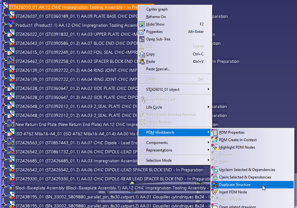
Once clicked, a list of the selected structure will open in the duplicate window, see the image below. As standard the whole structure will be set to duplicate, indicated with a green tick in the first column.
If this is not desired, documents can individually be set to ‘do not copy’ by selecting the row, then unticking the ’copy node’ check box and pressing ‘apply’ on the right side of the window. These nodes will then be highlighted with a red cross. Alternatively, the entire structure can be deselected by unticking the ‘duplicate all’ box at the top.
Note, documents that are not duplicated will still be copied into the new assembly.
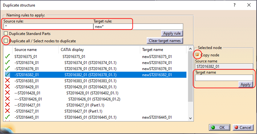
Target names must be defined for all duplicated items; however, these are only temporary as the new documents will automatically be assigned an ST document number on first save in the PLM. The names can be defined for all nodes by filling the “Source rule” and “Target rule” with a wildcard “*” as shown above. Alternatively, they can be defined individually using the box on the right.
Once finalised press okay and the duplicated structure will be opened in a new window. This can be saved into the PLM through a separate step, where new ST documents numbers will be assigned.
Associated drawings of the structure can be duplicated with the assembly. This setting can be enabled via the PWB Options window, found on the toolbar. If the duplication of drawings is enabled in this options window, they will be displayed in the list of objects to duplicate.


The log files can be very helpful to investigate some issues. They are required by the PWB supplier if we need to contact them.
Log level:
There are 3 log levels, 1,2 and 3. Working with the PWB logs should be rather transparent for your daily work with CATIA & PWB.
However, logs with level 1 or 3 can have a huge impact on the performances.
Therefore, and unless otherwise recommended from the CAD / PLM Support team, only activate level 2.
See the dedicated How To for the activation.
Log outputs:
Each time CATIA/PWB starts, a new log file is created in the cache folder ("C:\CERNPLM\prod\catia\USERLOGIN\_output_timestamp.log").
The log file is filled from the actions you do in CATIA. As long as CATA is running, the log file is under edition.
In case you have an issue with CATIA/PWB:
- first close CATIA (if still running),
- then go to C:\CERNPLM\prod\catia\USERLOGIN and sort the files per type.
- Create a zip file with all files which are not CAD files (basically, exclude all CATProduct, CATPart, CATDrawing & CGR files, and consider the . log, .xml, .txt & .csv).
- Only after the zip file is created, you can restart a new CATIA session.
Attention: if you restart CATIA before to collect the log files, most of them will be replaced by new empty ones.
Sending files:
Once you have the zip file will all the logs, send it to PLM Support (Service Now request) with a detailed description of your issue and your PC Name.
In case you had a CATIA crash ("Click OK to Terminate" message, or simply CATIA disappeared), please add the CATIA log file too.
This log file from CATIA is located here : C:\Users\%username%\AppData\Local\DassaultSystemes\CATTemp\
The file name is "Abend_Trace_ ... .txt" and is created at the time of the crash.
The PWB log files write down every action you do with the T-Systems PWB connector.
To be more efficient when investigating an issue, the PLM / CAD Support team, as well as the T-Systems team, need those files when an incident is reported. But for that, the log files must be activated previously.
And the activation must be done each time a new version of the Connector is deployed.
Here below the steps to follow:
- Make sure you have been granted with admin rights on your PC (automatically granted if you are Responsible and/or Main User in CMF)
- In a Windows file explorer, go to “G:\Workspaces\c\CAD_Support\Public\Enable-Disable PWB Logs”
- Unless other recommendation from the CAD / PLM Support team, launch “Enable PWB Logs Level 2”

- Allow the script to run by accepting all security requests
- In the Powershell window that will appear, check that you can see that the logs were properly configured:

Once activated, please read the dedicated How To to learn how to collect them in case a ticket must be sent to PLM / CAD support.
In the PWB it is possible to open a specific document in context, along with any documents that touch its bounding box in the specified context.
For example, if you have an engine and want to visualise only the parts that surround the crankshaft, this is quickly possible with this function. It prevents the requirement of having to open up the entire assembly, not only saving time but also improving the viewability (only see what is required).
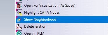
To proceed, first select a CATPart in a PDM Structures window. Then in the contextual menu, click on Show Neighborhood.
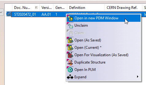
A query window will show up in which you will have to specify the context assembly. The context is the assembly in which the selected CATPart belongs to (the CATPart does not have to be a direct dependency of the assembly, it can be part of a sub-assembly), and in which surrounding geometry will be search for. Double click on the queried context.

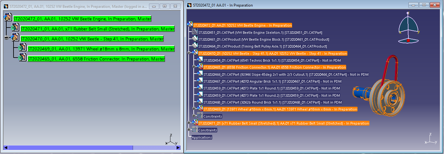
The result is a new PDM Structures Window, with the specified context assembly as the root object, that is filtered out with only the CAD Documents whose bounding boxes overlap with the bounding box of the original selected CATPart. You can open this reduced structure in CATIA. The rest of the structure that does not overlap with the main part, will be displayed in the CATIA tree, but no geometry will be loaded*.

Note: it is only possible to launch the neighbourhood query from a CATPart document, not from a CATProduct. However, it is possible to run several neighbourhood searches in a row. The content of each new PDM Structures Window can be opened and merged in the same CATIA geometry window. Also, the complete assembly can be opened in CATIA at any time.
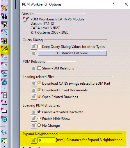
It is also possible to add a clearance around the bounding box of the selected CATPart, to find more CAD Documents. To modify the clearance value, please go to the connector options and enter the new value.
*If these ‘other’ documents have previously been opened in CATIA and their files are in your cache folder their geometry will also be loaded. They will be displayed as new documents, ‘not in PDM’. If the structure is saved these documents will be prompted to be saved as new references in the PLM. It is not recommended to save these. Instead, please close and reopen the structure normally if you need to make changes.
In the PWB it is possible to open on demand only certain selected nodes of the PDM structure in CATIA.
This may be useful when you only need to load a specific set of nodes from a heavy model, but would like to save it in context of the top assembly.
Firstly, open the assembly in the PDM structure window via the query tool, and expand the structure.

Then, instead of loading the complete structure with “Open” from the top assembly, it is possible to select any number of nodes (CATPart and/or CATProduct) in the tree and run the action “Open in Context” from the contextual menu (right click).

The complete PDM structure gets reduced to only the structure which contains the selected nodes and their parent node. This reduced structure is then opened to CATIA. The documents not selected for partial opening will be shown in the tree but their geometry will not be loaded*.
* However, if these ‘other’ documents have previously been opened in CATIA and their file is in your cache folder their geometry will also be loaded. They will be displayed as new documents, ‘not in PDM’. If the structure is saved these documents will be prompted to be saved as new references in the PLM. It is not recommended to save these. Instead, please close and reopen the structure normally if you need to make changes.
It is possible to book a new CDR before you even created the Drawing, in the case you want to create the drawing afterward and need to assign a specific CDR to it.
In this case, access the Design Code profile card either from the “Team search” menu in the Table of Content or from any other object assigned with the same Design Code.

From the Team profile card, either click on the following icon in the header,

Or click on “Book a new CDR” in the “Booked CERN Drawing References” tab ,in the right-hand side of the ribbon:

In the following open window, enter a reason for the booking action as well as all the required properties (marked with a red star). Confirm.

In case you are not using the "Sequence", the system will book the next available CDR deriving from the Design Code.
The CDR you just booked is now appearing in the “Booked CERN Drawing References” table and will be available to be set on a Drawing assigned with the same Design Code. Please follow the instructions of the following How to to assign that CDR to a Drawing.

Note:
You need to have one of the following roles to be able to book a new CDR: Contributor, Design Reviewer, or Equipment Owner.
General requirement:
Prior to using this functionality, make sure you have one of the following roles in the Design Code corresponding to the CERN Drawing Reference (CDR): Contributor, Design Reviewer, or Equipment Owner.
From the TitleBlock Editor
To set an existing CDR from the Title Block Editor (from any connector linked to the PLM), go to the Drawing Reference section and simply click on the "Set CERN Drawing Reference" button situated in the Drawing Reference section:

In the opening window, go to the "Booked Reference" tab.

There, you will find a list of existing CDRs corresponding to the Design Code associated with your CAD Document (as shown in the Design Code field). Simply choose the CDR you wish to assign to the CAD Document. If a CDR was previously cleared from the title block editor, it will appear in the list and be available for selection. If you wish to assign a CDR that belongs to a different Design Code, then just change the associated Design Code in this same window.
Note:
- The list of available Design codes correspond to the ones in which you have the roles mentioned in the General requirement section.
- Setting a CDR derived from a Design Code different from the one set on the Part is only permitted for non-master drawings. This does not have any impact on the access rights.
Confirm your selection, and make sure the chosen CDR appears in the "CERN Drawing Reference" field under the "Drawing Reference" section.
You can now click "Generate and save" — the selected CDR will appear in the title block and in the Profile Card of the CAD Document in the PLM.
From the CAD Document Profile Card (Creation or Edition):
To assign an existing CDR from the Profile Card of a CAD Document, make sure you are either in create or edit mode of the Profile Card.
Just below the Design Code, click the "Set CERN Drawing Reference" button.

In the opening window, go to the "Booked Reference" tab.

There, you will find a list of existing CDRs corresponding to the Design Code associated with your CAD Document (as shown in the Design Code field). Simply choose the CDR you wish to assign to the CAD Document. If a CDR was previously cleared from the title block editor, it will appear in the list and be available for selection. If you wish to assign a CDR that belongs to a different Design Code, then just change the associated Design Code in this same window.
Note:
- The list of available Design Codes corresponds to the one in which you have the roles mentioned in the General requirement section.
- Setting a CDR derived from a Design Code different from the one set on the Part is only permitted for non-master drawings. This does not have any impact on the access rights.
Confirm your selection, and make sure the chosen CDR appears in the "CERN Drawing Reference" field of the Profile Card.
Don’t forget to save your changes by clicking "Save" or "Done" from the CAD Document’s Profile Card.
From the Batch Import:
Coming soon...
More: How to book a specific CERN Drawing Reference before the creation of the Drawing?
If you encounter any issues during this process, please contact PLM support.
In case you need to change the authoring tool of a CAD Document, from AutoCAD to CATIA for example, click on the following button in the CAD Document Profile Card header:

The following window will appear, allowing you to change the Authoring Tool, add an Authoring Tool Version (optional) and a Native File.

Executing the authoring tool change on a CAD Document will automatically trigger the creation of a new version:
- Minor version of the CAD Document, in case the lifecycle state of the CAD Document is "In Preparation".
- Major version of the CAD Document, in case the lifecycle state of the CAD Document is "Approved", "Released" or "Replaced".
Note that the new CAD Document version creation can trigger the creation of a new minor or major version of its related Part.
The new CAD Document version will be created following these characteristics:
- The native file from the previous version of the CAD Document will be retained in the new version only if it is compatible with the selected Authoring Tool (e.g: you change the authoring tool from AutoCAD to BricsCAD) ; otherwise, it will be discarded.
- In case the native file of the previous version is not compatible, you must upload a new native file via the upload arrow (pointing up arrow) in the native file box .
If this CAD Document will be modified later with a PLM CAD Connector, its name should be “STref of this CAD Doc”. Example: ST0123456_01.CATDrawing or ST1234567_02.dwg. - The new version of the CAD Document will be marked as "not connector managed" and will be claimed.
In case you will save it using one of the PLM CAD connectors, it will then be set to connector managed.
Note: This “Change Authoring tool” command will not be available either in edit mode or during the creation of CAD documents from PLM.
Note 2:
Changing the authoring tool to CATIA will automatically update the classification of the CAD Document based on the uploaded native file type:
- .CATDrawing: Mechanical/Drawing
- .CATPart: Mechanical/Part
- .CATProduct: Mechanical/Assembly
Example use case:
A drawing was uploaded first as an AutoCAD drawing. Now, you are asked to create a new version of it, and you want to use CATIA for that.
- First go to the Profile Card of the drawing and hit the button to change the authoring tool.
- Select CATIA as authoring tool, and upload a new CATDrawing, locally saved and previously renamed as “STref of this CAD Doc”.CATDrawing
- Validate, then go to the current version of this CAD Document, and open it in CATIA
- Then, work as usual with your CATDrawing
As a result, you will be able to see in the CAD Document Version history that this CAD Document had several authoring tools.


If you require to quickly review a 3D CATIA model it may be advantageous to use the 'preview in CATIA' command.
This will open documents much faster compared to the standard method of opening native files in CATIA, or even opening the converted STEP files into SpinFire Ult desktop viewer.
Whilst documents can be opened as equally quickly in the integrated PLM web viewer, this program has limited analysis capabilities. So depending on the requirements 'preview in CATIA' may be preferable. This option also allows you to quickly merge several models in a single scene in CATIA.
Note, opening a document as a preview should only be done if you require read access. If any changes are necessary, the document should be opened fully through the 'normal' methods.
Opening method:
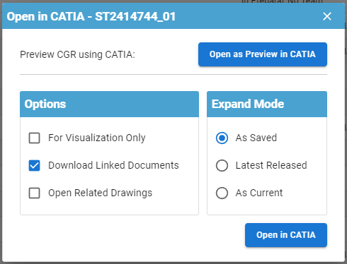
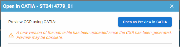
Any 3D CATIA file can be previewed in CATIA by pressing the usual CATIA icon from the dashboard or profile card header  and selecting the 'open as Preview in CATIA' button in the open options menu. If a CGR file is unavailable and waiting to be generated, it will be greyed out and a message will state that the CGR is not available yet. If a change has been made to the document and a new CGR file is being generated, a warning message will be displayed to warn you that the old CGR may be obsolete. Equally, this button is unavailable for drawings.
The file will be opened in a new window in CATIA. This will be displayed as 'Not in PDM' and you will be prompted to save them as new document numbers if you try to save. Please do not do this.

Please note, this method of opening differs from the 'for visualization only' option. The 'visualization only' simply renames the filename so it is not recognised by the connector, however it is still opening the native CATIA file type. This means it will be no quicker to load but you will be able to see all the modelling steps used to create the final model. Opening for preview uses a different filetype, CGR, which is much lighter and quicker to load, however you will only see the final model and you will not be able to interrogate the modelling steps.
Both methods can be used to open different versions of the same document number.
More:
Its important to know if your CAD structure contains 'non latest' versions of CAD Documents, especially if you need to work with the latest data, while the latest data might be available in SmarTeam only. Within the PLM and CATIA connector there are various ways you can check this.
- Through the use of dot icons in CATIA:
Orange, red and purple dot icons can be added to the standard CATIA symbols to indicate if a document is out of date. See this FAQ for more information on icons.
| Orange Dot: Not latest. At least one newer version exists only in SmarTeam (and not yet in the PLM). Note, the SmarTeam data sync process will occur each night, so the orange dot will appear the day after new SmarTeam data is created. | |
| Red Dot: Not latest. At least one newer version exists in the PLM, but all versions are available in the PLM. | |
| Purple Dot: The CAD document has out of date dependencies. |
- Through the 'Check dependencies' window in the PLM:
From a CAD documents profile card, it is possible to open up a tree structure of the CAD and check if any of the dependencies are ‘not current’. Click on the icon shown below in the profile card header.

The new opened window will use the same colour code as used in CATIA and described above to highlight if a document is out of date or has out of date dependencies. There is a counter on the right-hand side to total how many documents are ‘non-current’, either due to new versions available in the PLM or SmarTeam.

There are different filters available on the right, and a filter search field at the top. This box will filter for both document number and description.
- Through the PLM profile card header:
When viewing an individual CAD documents profile card, information will be displayed in the header if it is not the latest.
- If there is a new version available in the PLM (red dot), the following text will be displayed with a link to the latest version in the PLM:

- If it is the latest in the PLM but there is a new version available in SmarTeam (orange dot), the following text will be displayed:

- If its both not current in the PLM and SmarTeam (orange dot), there will be a link to the latest version available in the PLM, but it will also state there is an even newer version in SmarTeam:

- Through the CAD document attributes 'Is Current' & 'Is Current in SmarTeam'
When searching for CAD documents, or viewing them in a relationship grid from a profile card, you can see the 'Is Current' (in the PLM) & 'Is Current in SmarTeam' attributes

Design Codes are used within the PLM to grant users access rights to documents.
Within a Design Code there are different roles, which provide different access rights. A user can hold more than one type of role within a single Design Code.
|
Role |
Significance |
|
Viewer |
Read only access rights. |
|
Contributor |
Access rights to view, create and edit. Users with Contributor role can also launch Design Verification Workflows. |
|
Design Reviewer |
Rights to perform the ‘Design Documentation Check’ activity of the Design Verification Workflow. The Design Reviewer verifies and reviews designs making sure they are conform to the CERN design standards, inspects them, and adds annotations in a viewer without necessarily needing access to a CAD system. |
|
Equipment Owner |
Rights to perform the ‘Part Design Approval’ activity of the Design Verification Workflow. The Equipment Owner is responsible for checking that the requirements of the design are met. |
|
Senior Integrator |
Rights to launch ‘Valid for Integration’, ‘Approved by Integration’ and ‘Release for Integration’ workflows. |
| Viewer approved |
Users in this role will only be granted access to view the object, once it is in approved status. |
| Viewer released |
Users in this role will only be granted access to view the object, once it is in released status. |
The PLM can be opened through the Desktop app or in a web browser. The table below details the supported web browsers for different operating systems.
| Operating System | Supported Browsers |
| Windows 10 | • Edge • Firefox 78 ESR or 91 ESR • Chrome 103 (minimum) |
| Windows 11* | • Edge • Firefox 78 ESR or 91 ESR • Chrome 103 (minimum) |
| MacOS 10.15 Catalina | • Firefox 78 ESR or 91 ESR • Chrome 103 (minimum) |
* Whilst the PLM is supported in windows 11, CATIA currently is not. Therefore, if you need to use CATIA for any reason please ensure you are running windows 10.
There are three main different CATIA configurations that can be selected from the drop down in the CATIA launcher menu, small, large and equipment systems. Below details the main differences in their set up:
- Small Assembly – Cache is deactivated so all parts are opened in design mode, resulting in them taking longer to load. The 3D Tessellation accuracy is higher than in the large setting. Assembly updates are automatic.
- Large Assembly – Uses cache so parts are opened in visualisation mode. To edit, or view at a greater accuracy, the parts must be manually activated into design mode. The 3D Tessellation accuracy is lower than in the large setting. Assembly updates are manual.
- Equipment systems – The settings are primarily the same as the large except the assembly updates are automatic. There is also a difference in the available workbenches. Equipment systems contains two extra workbenches; HVAC design and piping design. However, it also has one removed, raceway design (an electrical cabling discipline).
- Large assembly- Beta - Uses the same settings as large assembly with a few modifications to improve CATIA's stability when working with very large models. The Q-checker is not available in this configuration.
Edit rights to a document is controlled via its Design Code and Responsible Project Group (RPG), which is set on its Parent Part. If a colleague requires edit rights to all the documents with one of these attributes, they should request access to these groups via the appropriate e-group. (Note you only need to belong to one of these groups to edit the documents, but you must belong to the Design Code contributor group to be able to edit the documents and initiate a validation process [Design Verification Workflow]).
However, if your colleague only needs to edit one particular document you can use the ‘Shared edit rights’ feature. A person with access to the document can use this feature to grant edit rights to another user on select documents, rather than all documents in a project.
On the profile card of the document navigate to the ‘Shared edit rights’ tab. From here use the add relation button to add the user that requires access. This person will be given contributor rights to this document only.
On the profile card of the document, in the ‘Shared edit rights’ tab, use the add relation button to grant your colleague edit right to this document only.

This feature is also available from a Part profile card. This will provide edit rights to the Part, but not to any of the CAD documents under it.
There are two ways of retrieving all the objects that you have claimed.
- Method one is to use the dashboard. From either one of the specific tabs (e.g CAD documents) or the All tab, click on the 'claimed by me' filter at the top. This will filter the results of the tab to show only objects that you currently have claimed.

- Method two is from a regular PLM search window. From the table of contents navigate to one of the objects, such as Part, and from here you can open a search window for this object type. Use the column 'claimed by' to filter documents claimed by you. The flag column confirms that these objects are claimed by you, through the presence of a green flag. (Note the column order is customisable to user preferences through drag and drop, so yours may differ from the screenshot below)
To unclaim all the objects in one go, use method 2 and highlight the results. (Press and hold the Ctrl key to select individual results. Alternatively, select a result then hold down the shift button and select another result, this will highlight all the documents in between.)
Once the required documents are highlighted right click to bring up the contextual menu. Click 'unclaim', to unclaim all the highlighted documents.

The CERN Drawing reference (CDR) on a drawing is usually generated from the Design Code applied to its parent Part.
However, on non-master drawings only, it is possible to apply a CDR that is not based on the parent Part.
This is to allow a drawing to be created with additional information that is not necessarily related to the main project, without affecting the access rights to the document. The access rights are still inherited from the parent's Part Design Code, and are unaffected by the differing CDR prefix.

To assign a CDR on a drawing from the title block editor press 'get new'. This will open the window shown below, where the design code used to generate the CDR needs to be confirmed. By default the design code used on the Parent part will be shown, but another can be chosen using the drop down button. Please note, only design codes where you are have the Contributor, Design Reviewer, Equipment Owner or Senior Integrator role will be shown.

For master drawings the design code selection is greyed out. To change the design code, and resultant CDR, on these drawings the design code must be changed on the parent Part first.

CATIA customised settings, such as shortcuts, can be saved in the PLM dashboard to be used when CATIA is reopened. This is also true for PWB setting changed in the options toolbar.
To save new customised settings, close the CATIA session in which the changes were made. Press the cog icon on the CATIA launcher to open the CATIA configurations window.

Enter a name for the new settings configuration. It will be saved and stored under one of the three main configurations that the CATIA session was originally opened under, and the settings were changed in.


Note the setting name may only contain alphanumeric characters and spaces, and be a maximum length of 64 characters. Configuration settings can also be deleted from this window by pressing the bin button next to them.
More: FAQ
To open a 3D CAD document in Spinfire Ultimate there is an icon available on each Profile Card. It is located on the thumbnail (the lower one, whilst the upper icon is used to display the web viewer): Open in Desktop Viewer.

The first time you click on this icon, a new SpinFire Ultimate instance (window) will be launched, and your CAD file will be open there.
If you later open a second CAD document in the viewer through the 'Open in desktop viewer icon', a pop up menu with appear:

"--> Open in a new window" will launch a new SpinFire instance:

"--> Open in a new tab in the first window" will open the selected CAD Document in a new tab of the FIRST instance of SpinFire that was launched.

"--> import to the active tab of the first window" will merge the selected CAD Document in the active tab of the FIRST instance of SpinFire that was launched:

With this last option, it is possible to merge multiple CAD documents that were made with different CAD authoring tools (ex: REVIT & CATIA V5).
The origin axis systems of all CAD Documents will all be coincident. But it is possible to move some components using the Transform dialog box.

Note: PLM desktop must be running, even if you are browsing the PLM using your web browser.
More about how to use SpinFire Ultimate: FAQ
In most situations all master CAD documents in a CAD structure are contained in the assembly’s BOM. However, there is a valid use case where this is not true.
For example, a component in a structure will be manufactured from a standard SCEM part, such as a long tube. The component is ‘Master’, but very simple and does not require its own drawing (dimensions will be placed on the assembly drawing). Rather than putting the modified CAD part in the BOM, the SCEM part is included instead to aid purchasing and manufacturing. See the example below.

To create a BOM structure that includes the Part of CAD C instead of CAD B, we can use the ‘marked as’ attribute in the PLM. There are different properties that can be applied to this attribute which alter how Parts are shown in the parent assembly BOM. The four different options are, ‘ ‘ (default), ‘IN-BOM’, ‘Not IN-BOM’ and ‘Phantom’. For this use case we will use the ‘ ‘ (default) and ‘Not IN- BOM’ property, but you can read more about the other attributes through the link at the bottom of this ‘How-to’.
The image below shows how to alter this property in CATIA. Select the document you want to change, then open the PDM properties window by selecting the icon on the connector toolbar. From here, there is a drop-down list to select the required marked as attribute.

For our structure above, we can set CAD B to ‘Not IN-BOM’, therefore it will not be included in BOM A. CAD D is left at the default option, meaning that because it is a master document, its Part will be included in BOM A. Finally, to add Part C this must be done manually in the PLM by following the steps below, but for more information please read the FAQ linked at the bottom of this page.
- Open the profile card of Part A. Put it into edit mode and navigate to the BOM tab at the bottom.
- Click on the ‘Add Parts’ button.
- A query box will be displayed, search for Part C and press ok.
- The part will be added to the BOM table.
It will be highlighted as manually managed. In addition, the quantity and position override boxed will be ticked as they cannot be computed from the CAD structure. The position box can be left empty, meaning it will be assigned the next available position, or a value can be provided. - If required, modify the quantity value. By default, it is set to 1.
- Click done on Part A’s profile card to save the changes.

Part A’s BOM is now updated and includes the required parts. The schematic below shows the resultant BOM structure compared to the CAD structure.

It is important to note, when creating a workflow to verify the structure, Part B must be added as a root object of the workflow, else it will not be approved and remain in preparation as a baseline.

BOM management FAQ: BOM management in CATIA / PLM
To comply with ISO Standards that has been implemented in the PLM platform, the Drawings Lifecycle States have been updated in EDMS after the data was synchronized with the PLM.
ISO 11442:2006 specifies a limited set of Lifecycle States, each with a specific meaning:
| In Preparation |
Default state for new object version. The object is being worked on. |
| In Review |
The object is in ongoing validation process. The object has been prepared and is subject to review, endorsement, checking and approval. |
| Approved |
The object is suitable for release but is not yet officially Released for its intended use. If a newer major revision is Approved, the previous one automatically becomes Replaced. In other words, only one Approved Major Revision is allowed. |
| Released |
The object has been prepared, reviewed, checked and approved. The object is allowed to be used for its intended purpose, meaning that the required item function has been validated. If a newer major revision is Released, the previous one automatically becomes Replaced. In other words, only one Released Major Revision is allowed. |
| Replaced |
The object is still available but has been replaced or superseded by another. |
| Withdrawn |
The object is no longer available as an active object. A withdrawn revision of an object is a revision that must no longer be used for any purpose. The transition to Withdrawn should be done with a specific workflow |
| Approval Rejected |
This lifecycle state, not compliant to the ISO standard, is needed to manage few special cases related to old migrated data. New data can not reach this lifecycle state. |
You can find the complete mapping in this presentation.
Some objects are classified as either Catalog or/and Standard components. All standard components are Catalog Components, but not all Catalog Components are Standard.
Both types are components that can be bought from a supplier catalog, as apposed to specifically designed for a CERN project. However, Standard components are compliant with standards such as ISO or DIN. They can be bought from any supplier so typically do not contain supplier information on their profile cards (some exceptions exist).
Both types of documents can easily be identified in the PLM by checking the two distinct properties; ‘Catalog component’ and ‘Standard’. These properties are attributed to both the CAD document and the Part. They are searchable in the PLM Dashboard and PLM search windows as shown below.
This said, some standard components are not flagged as such, for historical reasons. If you want to make an exhaustive search, we strongly recommend you to use the "Catalog Component" property only.


Additionally, the properties are shown in the PWB connector query window.

The properties are shown in the profile card header of both the CAD Document and Part.

For information of how to search for catalogue components that have a space in the document number, read the following how to :
How to search for documents with a space in the name?
See other 'searching' how-tos here
Short answer:
When searching in the global search box on the dashboard, you must put document numbers containing a space in quotation marks.

Long answer:
CAD Documents can be searched for either in the Dashboard or the dedicated CAD Document search window. In both windows there are different columns where filters can be applied to narrow down a search. For example you can specify a document number as shown below (simply enter the document number, no need for special characters).

On the Dashboard there is the additional option of using the global search box at the top, which will check in the following properties: Definition, Document Number, CERN Drawing Reference and External Reference. However, note that the settings of this search box are different to those of the the filter boxes. In this search box a white space ( ) is seen as an "AND" operator.
Therefore, for components which contain a space in the middle of the document number, in order to retrieve results you must place the 'number' inside double quotation marks (""), as seen in the first image.
To help with the transition from SmarTeam to PLM, we have put together a comparison between the different Specification tree icons. Some have remained the same, but others have changed or are new. Also note, previously with SmarTeam, the icons were viewable on both assemblies and CATParts. Using the PLM, they are viewable on assemblies only and CATParts open in their own window will have no PLM status icons.
|
Specification tree icons |
|||
|
PLM |
SmarTeam |
||
|
Name (nom) |
Icon (symbole) |
Name (nom) |
Icon (symbole) |
|
Unknown |
|
Unknown |
|
|
N/A |
N/A |
New |
|
|
Claimed by you |
|
Checked out by you |
|
|
Claimed by another user |
|
Checked out by another user |
|
|
Unclaimed |
|
Checked in |
|
|
Not latest |
|
Not latest |
|
|
Out of date dependencies |
|
N/A |
N/A |
|
Dirty status |
|
Dirty status (geometry) |
|
|
Not Synced |
|
Modified metadata |
|
|
Approved |
|
Released |
|
|
Released |
|
N/A |
N/A |
|
Replaced |
|
N/A |
N/A |
|
Withdrawn |
|
Cancelled |
N/A |
|
N/A |
N/A |
Obsolete |
|


Note, the lifecycle states do not correspond.
For more information on all the PLM/CATIA icons, please see the following documentation, FAQ.
Icons are used throughout the PLM and in the CATIA specification tree to quickly convey information. See the documentation below to find the explanation of each icon.
More: FAQ
A CAD document is made up of data, metadata. Some of this comes from CATIA such as the geometry, mass and material. Some of it comes from the PLM, Design code and RPG.
Two pieces of metadata can be changed in both the PLM and CATIA, the CAD definition and description. These two properties are mapped in both directions so can be modified in either platform and the data will be updated in the other. However, its important to understand when this information is transferred, so as not to loose any data.
- Data is pushed from the PLM to CATIA when a document is first opened.
- Data is pushed from CATIA to the PLM when a document is saved.
Why this is important?
If you have a document open in CATIA and change either the CAD definition or description in the PLM platform, these updates will not be pushed to the already open document in CATIA. The CATIA data will not be updated. Therefore, if the CAD document is subsequently saved in CATIA, the 'outdated' CATIA data will be pushed to the PLM overwriting the previous change.
Therefore, please do not change a documents metadata in the PLM if the document is already open in CATIA. Please do the changes in CATIA.
Note: If a document is modified in the PLM whilst it is open in CAD, when the CATIA tree is refreshed the definition will be updated because this displays data directly from the PLM connector. However, the CATIA data is not updated. This can be verified by viewing the data via right click > properties.
The batch import tool (drag and drop) can also be used to create new versions of CAD Documents already saved in the PLM.
To create a new version, in the 'Version a CAD document' column enter an existing document/Part number, or a CERN drawing reference number. Alternatively, by double clicking on the cell a search box will appear. From here you can search and filter to find the existing document you would like to version.
If a valid document is found, the version column will be populated with the document number, latest version and definition. In addition, some of the other columns will be automatically filled out with the metadata from the previous version, for example the sheet size and orientation. However, these can be modified if required.

Please note this feature can only be used with manually managed documents.
Once the import is launched, a new version of the document will be created and attached to the existing Part. The type of version (major or minor) is dependent on the lifecyle state of the previous version. Documents in a frozen state will have a major update, otherwise a new minor version will be created.