How To for PLM
You can create the Design Verification Workflow from the Part by clicking on the icon of the Workflow and then select Design Verification in the drop-down menu. Any already existing Design Verification workflows of the Part that are "In Preparation" will be proposed. Alternatively a new one can be created.

Once the Change Item profile card appears, select the Behaviour of the Workflow, fill in its Description and choose the Drawing Label.

Choose the Reviewer(s) who will perform the control(s), click on Done.
Launch the Precondition tests:

Then launch the Workflow:

The reviewers will receive a notification e-mail to invite them to perform the control.
Complete documentation: Design Verification Workflow FAQ
The Design Verification workflow is used to approve the Design data. Since we are working in Part Centric mode, this workflow allows to approve the Part and all its content. In other words, it will not be possible to approve a single Drawing by using this workflow.
If you want to know more details about designing the Workflow, please follow the document below.
Complete documentation: Design Verification Workflow FAQ
The baseline’s behaviour is determined by the expansion strategy and the filter it uses. The filter corresponds to the type of documents that are assigned (or not) to the baseline.
The only expansion strategy used is the top-down strategy. You can use the filter to assign a baseline to a part, a CAD document or a non-CAD document, provided that the status of the object from which it is generated is “In Preparation”. As stated in the “Baseline propagation” section, the baseline will not propagate to objects that have “Released” status. These objects are already frozen.
After a baseline has been created, the document(s) assigned to it cannot be edited or deleted (lifecycle status cannot be modified). The information about the baseline can be found in the document’s profile card.
The structure covered by the baseline cannot be edited and is frozen. The only way to modify documents is to create a new version of the document in question. Only the version used to generate the baseline is frozen. If a part has several versions, they are not all affected by the baseline.
To more details about this, please follow the document below (page 14).
You are able to create the baseline:
- from the document's profile card - click on the More ➞ Baselines ➞ Create Basic Baseline, the baseline's profile card opens in a new tab.
- from the document search pane, right-click on the line corresponding to the document that you want to include in the baseline, then click on More ➞ Baselines ➞ Create Basic Baselines.
Fill in all the necessary information and generate the baseline, click on the "Generate" button, which is enabled after the baseline has been saved.
To more about baselines, follow the document below.
The purpose of creating a baseline is to freeze any kind of structure (a part or a CAD document) along with all the documents belonging to that structure to which the baseline creator has access.
By creating a baseline, you can:
- save a specific version of a document at a certain moment in time,
- keep a record of how the design evolved,
- prevent a structure from being overwritten by future changes,
- create an official version to share with someone outside the Organization.
The FAQ document below will present the concept, describing its purpose, use, behaviour and consequences.
Most objects can be accessed from a “Properties” window. From there, the “Copy Link” button copies a link to the clipboard that you can then share, giving direct access to that object (in the version you selected) to anyone who receives the link*.
Click on the arrow to choose between the most recent version of the object (“Latest”) or the most recent approved version (“Latest Released”).

* This link is still subject to access rights restrictions; the person who uses the link must have the necessary rights to log into the platform and view the object.
You can navigate the platform using several different interfaces:
- PLM Explorer
- SmarTeam Explorer
- Icons panel
To know more about these interfaces, please follow the document below (page 34).
The “Life Cycle” command displays a map of the life cycle of the object from which the command is launched.
Documents, CAD documents and parts share the same life cycle.
The same map is therefore displayed for all three types of objects.

On the map, the object's current status is shown by a yellow square, not to be confused with the "In Review" status icon.

The “Versions” command grants you access to view all of the versions of a given object.

From the pop up window you can open an old version of the object in a new PLM window. It is also possible to compare two versions using the split screen function, the icon looks like: 
This function is not available for folders, which do not exist in multiple versions.
The "History" command shows you an object's modification history, across all its versions.

The history window displays the dates when actions were taken in relation to the object, as well as other information.
The fields can be customized using the "Refine" and "Display" / "Save Layout" buttons.

The “Where Used” command opens a new window showing where the selected object (in the selected version) is used. Structural links (children → parent links with objects of the same kind) are shown, as are links to objects of different kinds (e.g. a CAD document to a part, a CAD document or part to a folder, etc.). This is bottom-up navigation.
To see the example, follow the document below (page 27).
The “Structure Browser” function allows you to view the structure of the selected object. You can open or close the nodes by clicking on the + or – to the left of each node. With the blue + and – at the top left of the window, you can open or close all the nodes at once.
To read more about this, follow the document below (page 25).
The platform has a table of contents (TOC) on the left hand side. From here you can find all the options to navigate through the PLM to search and create objects.

The platform is navigated using tabs. Every time you open a document, a search or a link, a new tab opens next to the tabs that are already open.
It is largely the same for the four most common types of objects: parts, documents, CAD documents and folders. The menu also exists for other types of objects.
For more information on how to navigate around the PLM interface, and the icons used see the following FAQ.
There are several ways to access the search page, if you want to know more about this procedure, please follow the document below (page 7).
![]() Search Navigation and preferences in the PLM
Search Navigation and preferences in the PLM
See other 'searching' how-tos here
To open the quick search function, first open the Navigation Panel, then select the icon corresponding to the type of object you are looking for or use one of the shortcuts in the sidebar.
The quick search can be used to find an object if you know its reference parameter. This means that the quick search only works if you type in the first character(s) of the reference parameter.

![]() Search Navigation and preferences in the PLM
Search Navigation and preferences in the PLM
See other 'searching' how-tos here
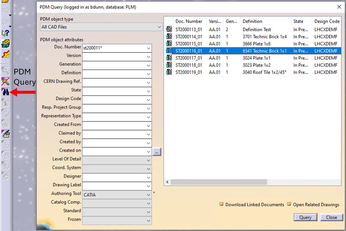
In CATIA, from the connector toolbar, clicking on the Query icon, you will be able to access the PDM Query dialog and to search for any CAD document previously uploaded to the PLM platform. Once the searched CAD Document has been found and selected, a double-click will open it in CATIA.
Note that the double-click corresponds to an Open as Current.
See the 'Opening' subgroup for related information
See more: Open CAD Document in CATIA
Any CATIA document saved in the PLM platform can be opened from there directly in CATIA. There are various methods, see below:
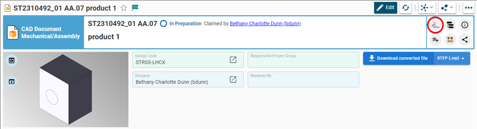
- From Profile card header
- From the PLM dashboard
- From the CAD Document Profile Card.
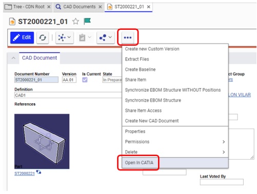
- From the profile card more menu
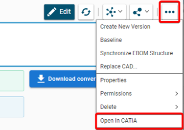
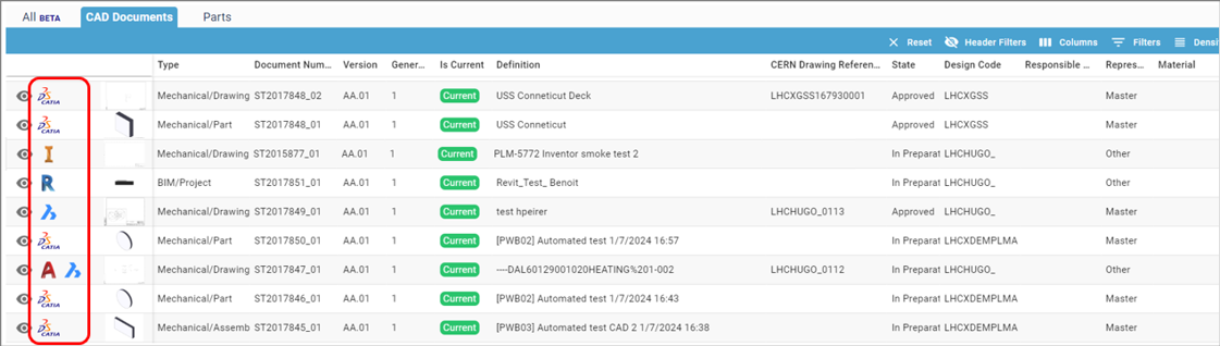
- From a search result grid, using the contextual menu.

See the 'Opening' subgroup for related information
See more: Open CAD Document in CATIA
For support, please send an email to plm-support@cern.ch.
A request will be automatically created in the Service-Now Platform. For urgent/blocking issues, please call the hotline: 160660
For CAD designers, it is also possible to report an issue from the PLM desktop application.

This way, the request created in Service Now will already contain some useful information for the PLM Support Team (PC name, date and time when the applications were launched, CATIA active document reference …).
This is the way to report the problems to be privileged.
Access to the CATIA connector is granted on request, therefore if you have not already done so please complete this form to work with CATIA. Prior to granting you access, we would ask for you to complete the relevant training, please see a link to the learning path to find the best suited course for you.
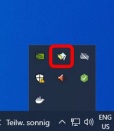
Once your computer is added in the NSC (to complete this process, the admin or the main user of the computer must accept a request sent via email), you will be able to install the CATIA connector via the CERN CMF installation manager, through the icon as shown in the image below.
Note that only Windows 10 physical machines managed by CMF are eligible for CATIA V5 installation.
To access CATIA via the PLM please press the CATIA icon in the top right of the dashboard screen.

Access to the CATIA connector is granted on request, therefore if you have not already done so please complete this form to work with CATIA. Prior to granting you access, we would ask for you to complete the relevant training, please see a link to the learning path to find the best suited course for you. Once you have been granted access you will have to download the required programs from CMF.
If you do not have the connector installed, or it is an out of date version, you will receive the following message when attempting to launch CATIA through the button on the PLM dashboard. This will remind you which applications must be installed and a link to CMF. There is also a link to documentation explaining the prerequisites required before running this application.

If CATIA is not installed the launch button will be greyed out.
Whilst the PLM is not able to support the multi-sheet drawings, here is the procedure to follow if you have a design that doesn’t fit only in one sheet of the drawing:
Note: the procedure refers to CATIA, but it can be applied for other CAD Tools (BricsCAD...) or BIM tools (Revit...) as well as for manual upload of Drawing (PDF...) in the PLM.
1. Create the drawing with all the needed views and run the Title Block Editor (get a CERN Drawing Reference). And if all these views cannot fit in one single A0 sheet, then,

2. Duplicate the drawing,several times if necessary (depending of the place that is required) and attach them to the same Part than the first one.The first Drawing will be the Master, while the additional(s) will be set as "Other".
In the description field of the additional drawing(s), you can put a note like: "Sheet 2 from LHCXDEMA1600"
Keep / remove and move the views on each Drawing.

3. Run the Title Block Editor and get a new CDR for each additional Drawing.
4. Add a note on each drawing and complete it, in the following way (* being the total number of drawings):

In CATIA, this note is available in the stickers Catalog.
See here how to add a sticker from the CATIA catalog
Please note the FAQ referred to in this how-to is under review. The first 3 sections of this FAQ refer to the methodology for Smt. For the required methodology for the PLM please refer to page 19 of this FAQ . Section 4 is relevant for both systems
Sometimes it is useful to compare two revisions of a document in CATIA. Due a limitation of the tool this is not possible to do it in a direct way (open) but there is a command and a workaround that can allow you to do this operation.
To learn more how to create it, please consult the following document.
![]() How to compare 2 different revisions of a document?
How to compare 2 different revisions of a document?
Note this FAQ is under review as it references Smt terminologies. However, the general advice remains the same, please unclaim your objects and assign a Design Code or RPG to allow others to continue using your work.
To ease the collaborative work with SmarTeam, there are some steps to validate before your CERN departure. In order to learn more about them, please check the document below and complete the check list presented before you leave CERN.
The PLM Responsible Project Groups (RPG) are in most of the cases synchronised with GMS groups (former "e-groups"). These can be managed by users on their own, without assistance from CAD/PLM support, using the GMS application.
Access the Profile Card of the RPG to check if it is synchronised with a GMS group.
Example:

If it is the case, search for the group in GMS and contact the owner / administrator of the group to be included.
Note: for the Design Code roles, the corresponding identities are still owned by CDD. In that case, contact plm.support@cern.ch to be added.