
CATIA R35 allows you to create multiple section views or section cuts by using a 3D sketched profile as your cutting plane. To save time and ensure consistency, you can reuse this sketched profile across other parts by copying it as a linked result, which maintains the associativity with your original geometry.
Defining the cutting profile directly in 3D, as opposed to just on the drawing, enables you to make the profile associative with the geometry, and therefore to drive this profile using dimensional constraints.
Creating a Section View Using a 3D Profile
1. In the Part window, click Sketch and select a reference plane (e.g., xy plane) to draw your cutting profile
2. Click Profile and sketch your profile. Apply dimensional constraints between the profile and other part elements to ensure associativity, then exit the sketcher 
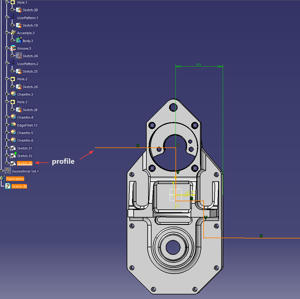
3. Switch to the Drawing window and click Update to refresh the view
4. From the Views toolbar, click Offset Section View (or another valid section icon depending on your specific profile type)
5. Select the profile on the 3D part. The cutting profile and a preview of the view will automatically appear on the front view
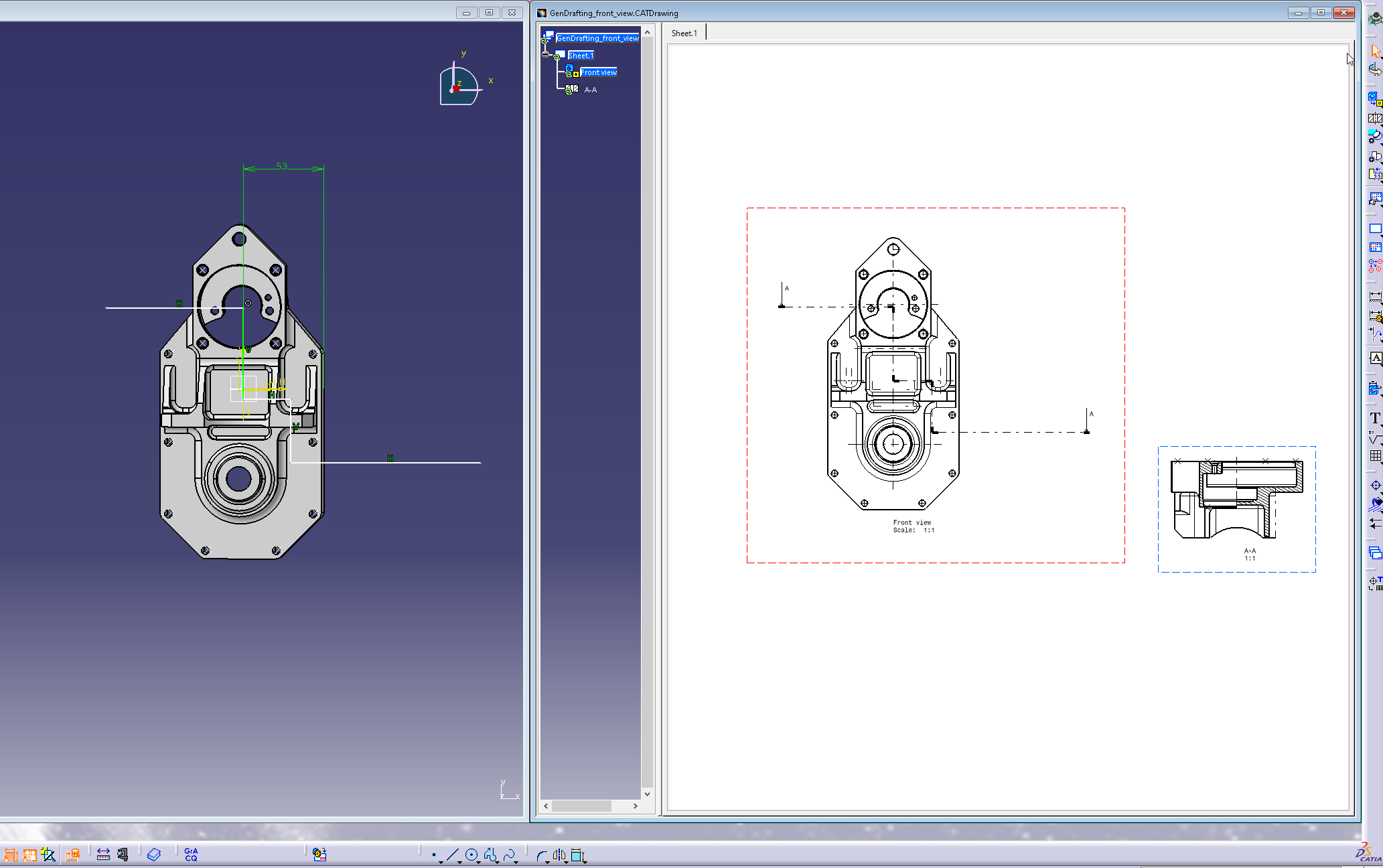
6. Click anywhere in the drawing sheet to generate and position the view
*Note: If the 3D profile is not valid for generating the chosen appropriate view (offset or aligned), you will not be able to select it and must select another section tool
To reuse this sketched profile in creating more sections for other parts, perform the following actions:
Reusing a Sketched Profile for Multiple Section Views
Ensure you have opened both the original 3D part containing the sketched profile and the new 3D part where it will be reused, along with its respective drawing
- In the specification tree, Copy the defined sketch in which the profile is created
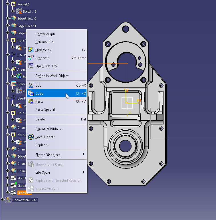
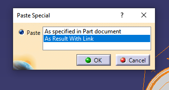
- Right-click the target part body where you want to create the new section view, and select Paste Special
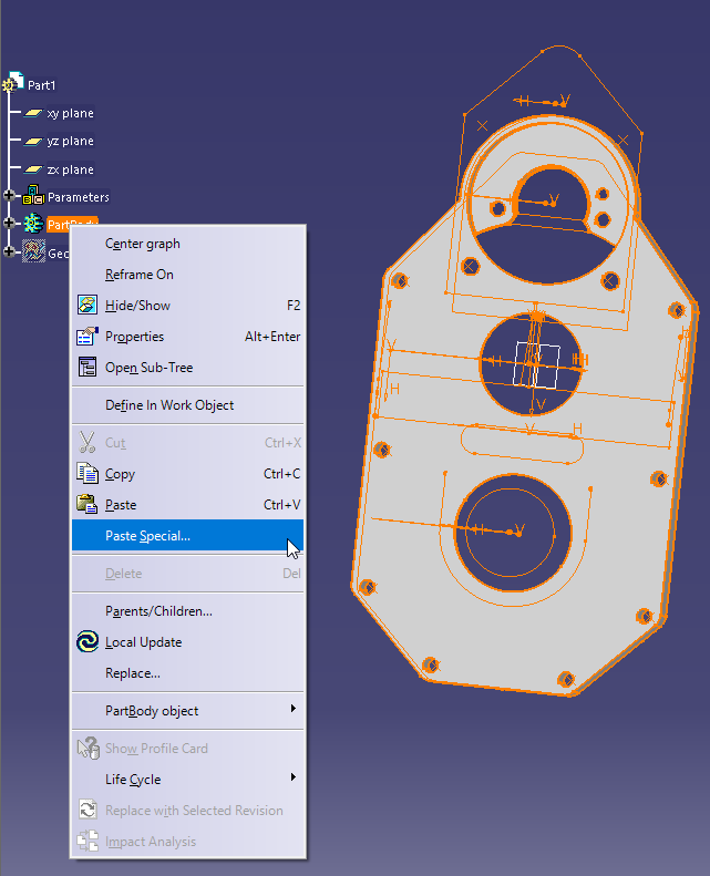
- In the Paste Special dialog box, select As Result With Link
- Switch to the Drawing window and from the Views toolbar, click either Offset Section View or Aligned Section View

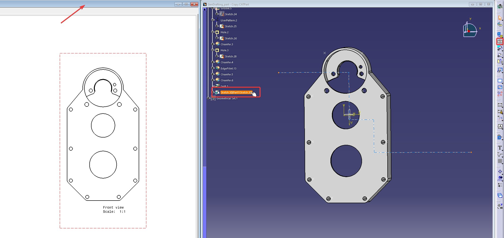
- Select the copied sketched profile. The cutting profile will be displayed along with a preview of the view.
- Click anywhere in the drawing sheet to generate and position the view.
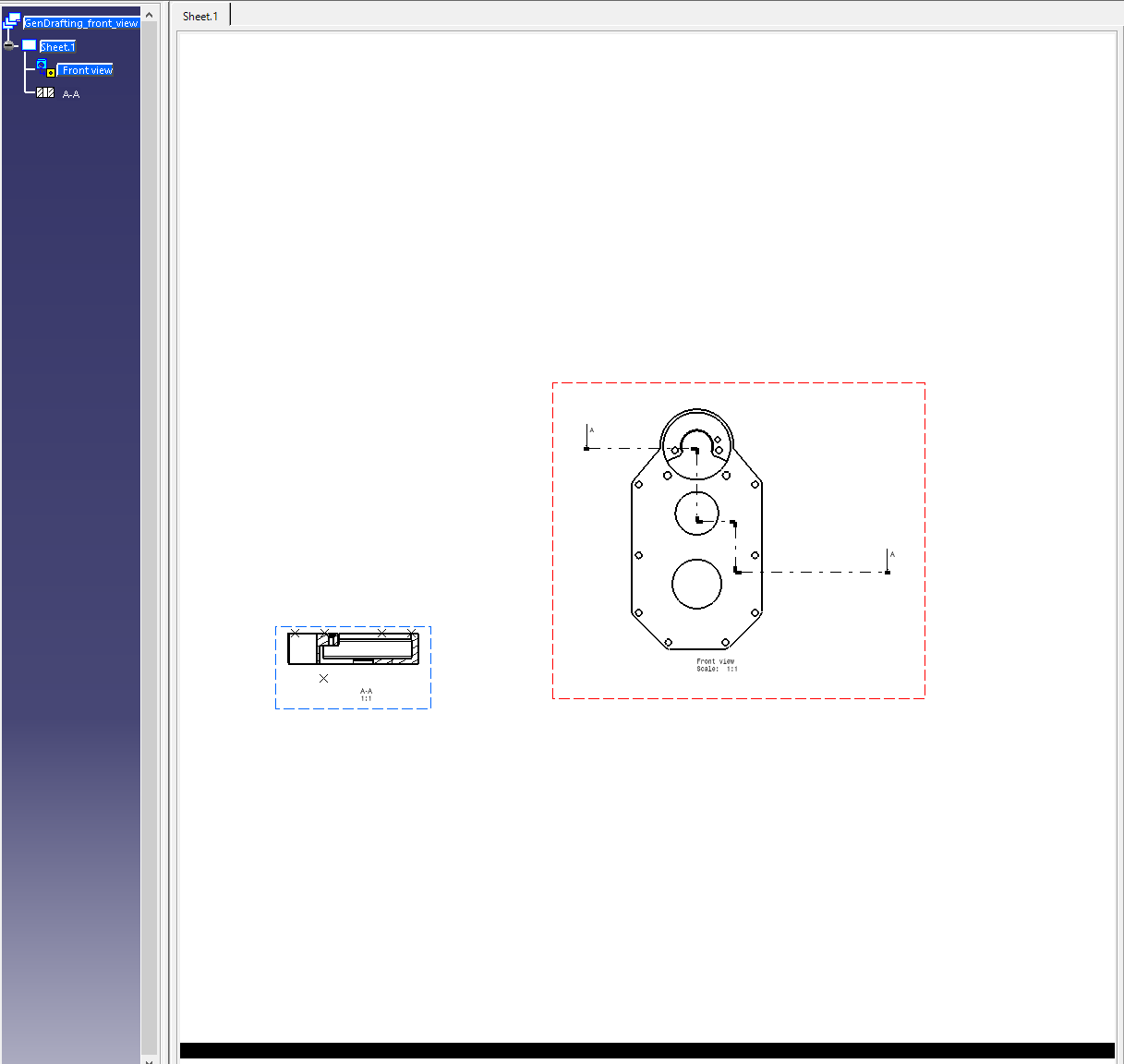
Important Notes:
- Associativity: You can modify the section view at any time by editing the original 3D profile. Always remember to click Update in the drawing window after making changes
- Invalid Profiles: When editing a 3D profile, ensure it remains valid for the type of section created (offset or aligned). If an edited profile becomes invalid, the updated drawing will display an error symbol instead of the view
More: FAQ