
How To
The platform has a table of contents (TOC) on the left hand side. From here you can find all the options to navigate through the PLM to search and create objects.

The platform is navigated using tabs. Every time you open a document, a search or a link, a new tab opens next to the tabs that are already open.
It is largely the same for the four most common types of objects: parts, documents, CAD documents and folders. The menu also exists for other types of objects.
For more information on how to navigate around the PLM interface, and the icons used see the following FAQ.
There are several ways to access the search page, if you want to know more about this procedure, please follow the document below (page 7).
 Search Navigation and preferences in the PLM
See other 'searching' how-tos here
To open the quick search function, first open the Navigation Panel, then select the icon corresponding to the type of object you are looking for or use one of the shortcuts in the sidebar.
The quick search can be used to find an object if you know its reference parameter. This means that the quick search only works if you type in the first character(s) of the reference parameter.

Search Navigation and preferences in the PLM
See other 'searching' how-tos here
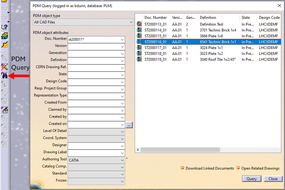
In CATIA, from the connector toolbar, clicking on the Query icon, you will be able to access the PDM Query dialog and to search for any CAD document previously uploaded to the PLM platform. Once the searched CAD Document has been found and selected, a double-click will open it in CATIA.
Note that the double-click corresponds to an Open as Current.
See the 'Opening' subgroup for related information
See more: Open CAD Document in CATIA
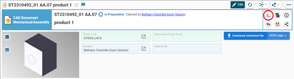
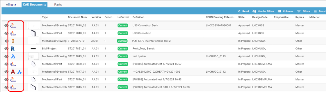
Any CATIA document saved in the PLM platform can be opened from there directly in CATIA. There are various methods, see below:
- From Profile card header
- From the PLM dashboard
- From the CAD Document Profile Card.
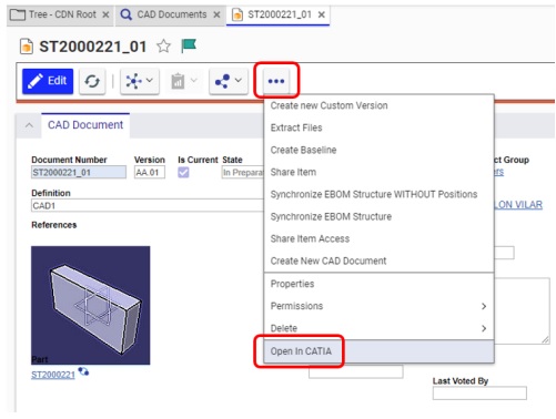
- From the profile card more menu
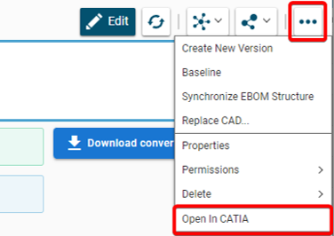
- From a search result grid, using the contextual menu.

See the 'Opening' subgroup for related information
See more: Open CAD Document in CATIA
For support, please send an email to plm-support@cern.ch.
A request will be automatically created in the Service-Now Platform. For urgent/blocking issues, please call the hotline: 160660
For CAD designers, it is also possible to report an issue from the PLM desktop application.

This way, the request created in Service Now will already contain some useful information for the PLM Support Team (PC name, date and time when the applications were launched, CATIA active document reference …).
This is the way to report the problems to be privileged.
Access to the CATIA connector is granted on request, therefore if you have not already done so please complete this form to work with CATIA. Prior to granting you access, we would ask for you to complete the relevant training, please see a link to the learning path to find the best suited course for you.
Once your computer is added in the NSC (to complete this process, the admin or the main user of the computer must accept a request sent via email), you will be able to install the CATIA connector via the CERN CMF installation manager, through the icon as shown in the image below.
Note that only Windows 10 physical machines managed by CMF are eligible for CATIA V5 installation.
The main purpose of the toolbox is to design a multi-layer's coil or magnet spacers defined by points coordinates stored in a text file. You can also use this tool to estimate the quality and conformity of generated parts by searching intersection between correspondent coils and spacers. Tool can be used to check the quality of generated spacers by finding distance between the points from text file and the used ones for the design. Tool can be used for exporting constructed data in STEP format.
If you have more questions about this, please check the document under.
To import you need the "Part Template" tool. This can create some 3D points in Catia V5 from their coordinates stored in one Excel file. The created points can be automatically renamed if the name information is available in the Excel file. An optional feature allows building straight lines between every point.
If you want to know details, please check the document below.
The tool that you have to use is a "Power Copy". To use it, a Part must be activated. If you want to know more details, please open the document which is under.
This tool generates a CATPart from a CATProduct, using the "Generate CATPart from Product..." command. Then the tool scans the original Product to search for the materials associated to the parts. It is also possible to run this macro from an existing CATPart generated previously, if the corresponding Product is also opened in Catia V5 to add the material and definition parameters.
If you want to know more about this tool and how to generate this process, please follow the document below.
The "Optimization" workbench is available in Catia V5. It is possible to use it to solve more or less complex problems. You will find in the document below some simple examples in which some optimizations are used and some information on how to put them in place.
The CATIA Knowledgeware regroup a lot of functions: rules, optimizations, templates... that allow you to create generative tools or parametric constructions. Most of the common functionalities we can use in CATIA are contained in "Product Synthesis" solutions.
To start, go to the "Mechanical Design" and then to the "Generative Sheetmetal Design" workbench. Click on the icon and specify the correct parameters of the sheet that you are going to work with: "Thickness", "Default Bend Radius" and "Bend Extremities". The "Sheet Metal Parameters" feature should be added in the specification tree.
If you want to see step by step how to do it, please follow the document below.
The following document has an explanation how to do this step by step. Please check it if you want to know more.
The "Surface Curvature Analysis" is used to find the curvature of the surface or the face of a solid. You can perform analysis in "Part Design" as well as in "Generative Shape Design". If you want to see how the procedure should look like, please open the document below.
Split is an operation where one element is cut by another element.
Trim is an operation in which two elements cut each other mutually.
If you want to see more details and differences between these two functions, please check the document below.
To get the surface from land contour lines you need to proceed from the isolation of the relevant geometry, then the improvement of the quality of the geometry and then the generation and extraction of 3D points. Then you should transform the 3D points into the cloud of points, generate a mesh and then finally auto create a surface feature. If you want to know more details about it, please follow the link below with explanation.
Distance analysis tool could be used to measure distance between surfaces which are very close to each other. The distance is computed in several points so as result we will get the distance distribution between chosen surfaces. You can find "Distance Analysis" tool in "Shape Analysis" toolbar which is available in “FreeStyle” workbench. To find it, follow the instructions on the document below.
You can now create planes between two existing planes at once.
Follow the instruction to do this:
- Click on the "Replication" toolbar.
- Find the icon "Planes Between".
- When the dialog box appears, select two planes between which the new planes must be created (it cannot be parallel).
- Indicate the number of planes.
- Click "Preview" to see the plane created.
- Click "OK".
- Planes are added to the tree specifications.
For more details, please check the document below.
For objects with features that are symmetrical in the thickness direction, a middle surface can be created using functions from the Generative Shape Design (GSD) workbench. There are several options on how this can be done.
In the following document you can find three scenarios that a user can basically come across:
- All of the object’s relevant features are symmetrical in the thickness direction.
- Some of the object’s relevant features are asymmetrical in the thickness direction.
- It is possible to create the solid from the surface rather than the other way around.
To know it better, please check the methodology in the link.
A 3D curve can be created in space or lie on a geometrical element, or both. When the curve lies on a geometrical element, associativity can be kept. It is also possible to edit, delete or add points when creating the curve, or after. A 3D curve is a very fast and flexible tool which is really different from a "Spline".
- route electrical wires,
- work with Bezier Nurbs,
- create a guide curve for a sweep or a rib.
From the following document, you will learn new possibilities about 3D curve from "FreeStyle" workbench.
The 3D curve function is available in the Freestyle workbench. With the 3D curve function, it is possible to create associative curves in which you can add or remove points during the creation of the curve and also later.
If you want to know more details, when to use it or how to modify it, please check the document below.
See also: How to create an advanced 3D curve?
If you want to learn how to create a run and place a "Pipping Part", please study the document below which inside you can find an example how to design it.
Often enough, there is a need to switch between a 2D opened in CATIA to its corresponding 3D. In order to facilitate and quicken this task, it is possible to open the 3D directly from the 2D. To know more about this procedure, please check the document below.
The document below is only applicable to the Integration team.
For the other users, if an A0 sheet is too small, please follow this link: CLICK.
Due to a limitation in CATIA V5 it is impossible for users to place multiple orthogonal leaders for geometrical tolerances.
The workaround consists in:
- Hold down Shift key before selecting the first reference of the geometrical tolerance, this will create the first leader.
- Right click on the tolerance and select "add new leader" and select other reference (without holding Shift).
- Right-click on the extremity of the arrow (yellow mark) and select "Add a Breakpoint", this will add yellow mark on the leader where the breakpoint is located.
- Hold down the Shift key and try to move the newly created Breakpoint (new yellow mark).
- The breakpoint will jump to the main geometrical element leader and it looks like a new perpendicular leader.
- You can right-click on the Breakpoint again and select "Rigid", this will help to keep it in place.
Each time you want to adjust the perpendicularity of the leader created via the breakpoint, move it with pressed down Shift key and the point will adjust perpendicular to the main geometrical element leader.
Whilst the PLM is not able to support the multi-sheet drawings, here is the procedure to follow if you have a design that doesn’t fit only in one sheet of the drawing:
Note: the procedure refers to CATIA, but it can be applied for other CAD Tools (BricsCAD...) or BIM tools (Revit...) as well as for manual upload of Drawing (PDF...) in the PLM.
1. Create the drawing with all the needed views and run the Title Block Editor (get a CERN Drawing Reference). And if all these views cannot fit in one single A0 sheet, then,

2. Duplicate the drawing,several times if necessary (depending of the place that is required) and attach them to the same Part than the first one.The first Drawing will be the Master, while the additional(s) will be set as "Other".
In the description field of the additional drawing(s), you can put a note like: "Sheet 2 from LHCXDEMA1600"
Keep / remove and move the views on each Drawing.

3. Run the Title Block Editor and get a new CDR for each additional Drawing.
4. Add a note on each drawing and complete it, in the following way (* being the total number of drawings):

In CATIA, this note is available in the stickers Catalog.
See here how to add a sticker from the CATIA catalog
A drawing can be called “too large” when the native file size is a number with more than 6 digits. Unfortunately, there is not a perfect solution but in the document below there are different methods and options that depending on each case can be used to generate a lighter drawing. Please follow the link to understand it better.
In some cases, you can use in the "Tools Palette" and it can be recognized during the creation of the dimensions. It is always possible to add these points manually and after using them, create the dimensions. The blue lines and the intersection points are not visible when the document is outside CATIA (printed or in CDD).
If you want to understand more details and how to represent the prolongation lines to the intersection point, please open the following document.
- Select one or more holes in the drawing.
- Click "Hole Dimension Table" in the dimensioning toolbar.
- The Axis System and Table Parameters should be displayed.
To know more about the dialog box and what to type or select, please check the following document.
In CATIA it is not possible to add the symbol envelope direct to a diameter.
Here there is a workaround to add it if the dimension:
- is not a diameter or a radius
Properties ➞ Dimension Texts ➞ Main Value ➞ click on the symbol - is a diameter or a radius
Properties ➞ Dimension Texts ➞ Prefix Suffix ➞ choose the group of symbols (first icon) ➞ Main Value ➞ click on the symbol
If you want to see step by step how to do it, please follow the instruction which is in the document below.
The drawing standard is stored in the drawing upon the creation, this standard 'copy' is kept independently this means it will not automatically update when the standard settings of CATIA change.
There is a procedure step by step how to do it:
- Open and Check-out the Drawing.
- Go to the File ➞ Page Setup.
- In Page Setup window select the standard of the drawing like ISO_CERN.
- Push the "Update" button.
- Update the elements which changed in the standard.
If you want to know more details about this procedure, please check the document which is under.
You can create a section view using a 3D profile or a plane in the 3D, as sectioning element. Using a 3D element to define a section view makes possible to constrain this element with the geometry of the part. The profile section will automatically be kept up to date if the 3D geometry changes. Check the document below if you need more information how to create it.
The colors of dimensions are controlled by the "Analysis display mode". Select this option to display dimensions using different colors according to their status (not-up-to-date, isolated, fake, etc.).
In the document below you can find all configurations of colors.
Due to a Catia limitation, the "3D Clipping View" function from the "Drafting" workbench is not compatible with the "Do not cut in section views" options, which are in the "Drafting" tabs of the 3D properties or in the "Overload Properties" on the 2D view.
If you want to study alternatives, please check the document below with explanations.
- Open the "Link Modification" window from the view.
- Select the scene in the 3D.
- Switch the scene in the "Pointed elements".
- Validate and update the view.
If you want to see step by step how to do it, please click on the link which is under.
On a drawing, it is possible to display extra digits on the dimensions for specific purposes (e.g.: to highlight that a dimension has not been rounded on the drawing).
If you want to know more this topic, please check the following document.
Changing the digits number after the decimal separator on exact dimensions
- Click “Free Hand Selection Trap” or select all circles.
- Click on the “Center Line with Reference” icon.
- Select the center reference of the holes.
After the creation of an axis system or a thread using the "Axis and thread" functions, it is possible to resize this axis system. By default, if you drag one of the extremities, both axis will be resized. Holding the Ctrl button and dragging one extremity will change the size only of the selected axis.
In CATIA, it is not possible in an approximate mode view to create a dimension relying on a 3D point created in the GSD workbench. The document below will show you which are the workarounds to this limitation.
To launch the TRACEPARTS Web from CATIA, click on the Icon:

This will open thee web page with list of companies' logos.
To find the component that you are looking for select the main filter or the starting letter of your desired category.
You can also skip it and scroll down until you find the company that you need.
When finally you find the page and select it, then click on the family you want and choose the references.
Under CAD models tab you can select CATIA V5 as your tool and then approve it.
This following document explains how to use the new Web TRACEPARTS (2021). Please check it to understand more how it works.
The scene tool in the “Assembly Design” workbench allows you to create multiple states of your model. By doing so, it enables you to study a variant of your assembly by defining specific component positions and specific attributes. The following document covers the main advantages and limitations of this tool.
A "Scene" is an alternative view of an assembly in a defined state. It enables you to study a variant of your Assembly by defining specific component positions and specific attributes. Please follow the document below to understand more details.
If you don't have an icon "Replace Component" in CATIA tools, find it this way:
- Click on the Part or Product in CATIA tree or "Edit" on the menu.
- Find the option named "Components".
- Choose:
- option "Replace Component in Session" which offers you as replacement the elements that are opened in the CATIA session,
- option "Replace Component" is the command which opens the search editor to find in SmarTeam the replacement.
The following document will show you more information about this function.
A positioning Matrix allows to place a component (Part, Component, Product) in space, relative to a higher component level, which will contain this matrix. If you want to understand more details, please click on the following document.
In the following document there is an example that will show you step by step how to save it.
- Edit the fix component constraint (double click on the constraint in the 3D or the tree).
- The following dialog box appears, then click on "More" and let the "Fix in space" checked.
- At that point you can change the values of translation and rotation (you can also change these values from the properties of the constraint).
- The component will take its new place.
- The components that were linked by constraints will update also.
If you want to know more, please check the document below.